Table of Contents
Advertisement
Quick Links
Advertisement
Table of Contents

Related Manuals for LAUREL LTS


Summary of Contents for LAUREL LTS
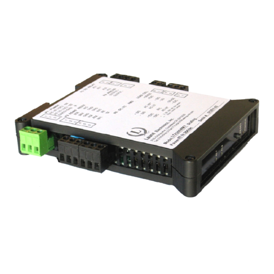
- Page 1 Model LTS RS232 OR RS485 SERIAL INPUT, ANALOG OUTPUT TRANSMITTER Modbus or Custom ASCII Protocol OWNERS MANUAL LAUREL Electronics Inc. 3183-G Airway Ave, Costa Mesa, CA, 92626, USA Tel: (714) 434-6131 Fax: (714) 434-3766 • Website: www.laurels.com...
-
Page 2: Ordering Guide, Serial Input Transmitter
1. ORDERING GUIDE, SERIAL INPUT TRANSMITTER Configure a model number in this format: LTS60, CBL04 LTS6…Transmitter with 4-20 mA, 0-20 mA, ACCESSORIES 0-10V or -10V to +10V isolated analog CBL04……RS232 cable, two 3-pin connec- output, RS232 or RS485 serial data tors on transmitter end, DB9 input, and dual 120 mA solid state connector on computer end. -
Page 3: Table Of Contents
TRANSMITTER FIELD WIRING ..................7 JUMPER SETTINGS ......................8 PROGRAMMING YOUR TRANSMITTER ................10 LTS STREAMING DATA INPUT MODE WITH CUSTOM ASCII PROTOCOL ......12 LTS COMMAND MODE WITH CUSTOM ASCII PROTOCOL ..........21 LTS COMMAND MODE WITH MODBUS RTU PROTOCOL ..........22 USING DIAGNOSTIC TOO QMODMASTER ................ -
Page 4: Introduction, Serial Input Transmitter
USB port of a PC. The LTS is not plug and play. The format of the strings being received must be known in advance, including non-printing control characters. If you do not know the format of your ASCII data, contact tech support of the manufacturer of the sending device. -
Page 5: Receiving & Unpacking Your Transmitter
4. RECEIVING & UNPACKING YOUR TRANSMITTER Your transmitter was carefully tested and inspected prior to shipment. Should the transmitter be damaged in shipment, notify the freight carrier immediately. In the event the transmitter is not configured as ordered or is inoperable, return it to the place of purchase for repair or replacement. Please include a detailed description of the problem. -
Page 6: Safety Considerations
5. SAFETY CONSIDERATIONS Warning: Use of this transmitter in a manner other than specified may impair the protection of the device and subject the user to a hazard. Visually inspect the unit for signs of damage. If the unit is damaged, do not attempt to operate. Caution: •... -
Page 7: Transmitter Field Wiring
6. TRANSMITTER FIELD WIRING - 7 -... -
Page 8: Jumper Settings
7. JUMPER SETTINGS Serial Signal Duplex Jumpers Termination Resistor* E6 a = Transmit Full None E6 c = Receive RS485 Half E6 b + d** E6 c RS232 Full None None The termination resistor jumper settings should only be selected if the transmitter is the last device on an RS485 line longer than 200 feet (60 m). - Page 9 WHEN TO CHANGE JUMPERS Your transmitter case does not need to be opened if jumpers have already been set by your distributor. Otherwise you will need to open the case and either set jumpers or verify that the factory default jumpers positions will meet your needs. Factory default jumper settings are for RS232 input and 4-20 mA output.
-
Page 10: Programming Your Transmitter
8. PROGRAMMING YOUR TRANSMITTER OVERVIEW LTS serial input transmitters are programmed using a PC with a USB port and our free Instru- ment Setup (IS) software, which provides a graphical user interface. This software allows uploading, editing, downloading and saving of setup data. To interface the LTS to the PC, two... - Page 11 After selecting a screen input field, pressing the F1 key will bring up detailed help information for that field. The LTS serial-to-analog converter needs to receive streaming serial data or commands from a Master. It cannot act as a master and send commands or ASCII characters.
-
Page 12: Lts Streaming Data Input Mode With Custom Ascii Protocol
Signal Input, Gate Time, Filter and Power-On Total. Under Display, select one of the Remote operating modes shown. Please see the screen captures below for more information. Remote A is an addressable input mode for up to 31 LTS units. The received ASCII text strings must be in a format like *#KSDDDDDD.A<CR>... - Page 13 <CR> = Carriage return character. A <LF> <LF> <LF> <LF> line feed character may be appended but is ignored. Remote S is like Remote A but is not addressable. The absence of addressing makes Remote S faster than Remote A but limits it to point-to-point connections. The received value is stored where it may be selected for Alarm comparisons.
- Page 14 Note: The LTS is not plug and play. The format of the strings being received must be known in advance, including non-printing control characters. If you do not know the string format, contact tech support of the sending device's manufacturer, or use a terminal emulator program like HyperTerminal, PuTTY or RealTerm to view the actual trans- mitted characters.
- Page 15 SETTING UP COMMUNICATIONS (REMOTE A & S STREAMING INPUT MODES) The above screen will appear under the Communication tab if Remote A or Remote S has been selected as Display Type under the Input+Display tab. These two modes are not able to extract data from an ASCII string that contains multiple data values and non-numeric characters.
- Page 16 SETTING UP COMMUNICATIONS (REMOTE C STREAMING INPUT MODE) The above screen will appear under the Communication tab if Remote C has been selected as Display Type under the Input+Display tab. This mode is able to extract data from ASCII strings that contain multiple data values and non- numeric characters.
- Page 17 SETTING UP THE ANALOG OUTPUT Under the Analog Out tab, set Source to Item 3. Under Range, select 0-20 mA, 4-20 mA, 0-10V or -10V to +10V as your desired analog output. Enter your Lo Range Reading and Hi Range Reading.
- Page 18 SETTING UP RELAY ALARMS OPERATION Dual AC/DC solid state relays rated 120 mA are standard for alarm or setpoint control and are independently set up via the “Relay Alarms” tab. Set “Alarm Source” to “Item 3” as illustrated. For online help with any data entry field, press the F1 key. •...
- Page 19 • Deviation. A positive number that can be added or subtracted from the setpoint, depending on the Deviation Type, to determine when an alarm becomes Active or Inactive. • Alarm Source. Depending on the Signal Input Mode and Function selected under the Input+ Display tab, the alarm can be assigned to any of up to three Items, for example to Item 1 (A rate / B rate), Item 2 (A rate), or Item 3 (B rate).
- Page 20 • Alarm Type. Selections are Non-Latching and Latching. Under Non-Latching, the relay is only closed (or open) while the Alarm State is Active. Under Latching, the activated relay remains closed (or opens) until reset regardless of the Alarm State. Resetting is normally achieved by temporarily grounding one of the transmitter’s control inputs, which has been set to Function Reset under the “Input+Display”...
-
Page 21: Lts Command Mode With Custom Ascii Protocol
10. LTS COMMAND MODE WITH CUSTOM ASCII PROTOCOL Laurel’s Custom ASCII protocol allows the LTS to receive data in the form of ASCII text strings, which can be either in a streaming Continuous Mode or in a Command Mode, as described in the user manual at https://www.laurels.com/downloadfiles/serialcom2.pdf. -
Page 22: Lts Command Mode With Modbus Rtu Protocol
006C generate 4, 12 and 20 mA analog outputs. Example on how to send the value 999999 to Item #3 of an LTS using the Modbus protocol: 1 10 00 6B 00 02 04 00 0F 42 3F F4 87... -
Page 23: Using Diagnostic Too Qmodmaster
12. USING DIAGNOSTIC TOOL QMODMASTER 1. ABOUT QMODMASTER qModMaster.exe is a freeware Windows program which allows a PC to serve as a Modbus Master. It is an easy-to-use tool to verify communications, send requests to Modbus Slaves, and view their responses. qModMaster works well with Base 0, but not with Base 1, so use it only with Base 0 and subtract 1 from the Register addresses listed in our Modbus Manual for Counters. - Page 24 Note that that the entry in counts to be sent to Item 3 can be in Hex or Dec formats. Under Commands Connect , press to make the data connection. The Bus Monitor should show Tx and Rx “values written correctly.” For information on these values, please see our Modbus Manual for Counters at https://www.laurels.com/downloadfiles/Modbus-Manual-CTR.pdf.
- Page 25 3. EXAMPLE: USE MODBUS COMMANDS TO CONTROL TWO RELAYS Using BASE 0 addressing, alarm relays are controlled by writing to holding register 0x006F. Bit 0 controls Relay 1. Bit 1 controls Relay 2. First Alarm1 is forced by writing 01 01 01 01 to holding register 0x006. This turns Relay1 on. Then Alarm2 is forced by writing 03 03 03 03 to holding register 0x006.
- Page 26 - 26 -...
-
Page 27: Specifications, Lts Serial Input Transmitter
13. SPECIFICATIONS, LTS SERIAL INPUT TRANSMITTER Serial Data Input Signal Levels ........RS232, full-duplex RS485, half-duplex RS485 (selectable) Protocols ....... Modbus RTU, Modbus ASCII, Custom ASCII (software selectable) Custom ASCII Operating Modes .......... Streaming Mode or Command Mode Modbus Operating Mode ..................Command Mode Serial Connector ................ -
Page 28: Warranty
In the event of a defect during the warranty period, the defective unit may be returned to the seller, which may be Laurel or a Laurel distributor. The seller may then repair or replace the defective unit at its option. In the event of such a return, freight charges from the buyer shall be paid by the buyer, and freight charges from the seller shall be paid by the seller.
Need help?
Do you have a question about the LTS and is the answer not in the manual?
Questions and answers