
Subscribe to Our Youtube Channel
Related Manuals for Multi aqua MACH-060-1

Summary of Contents for Multi aqua MACH-060-1
- Page 1 MACH Heat Pump Air-Cooled Chiller Heat Pump Air-Cooled Chillers for Global Residential and Light Commercial Microclimates...
- Page 2 MACH NOMENCLATURE BREAKDOWN MACH-060 - 1 Air-Cooled Chiller 060= 60,0000 BTUH Voltage 1 = 208/230-1-50/60 Available Model Numbers MACH-060-1...
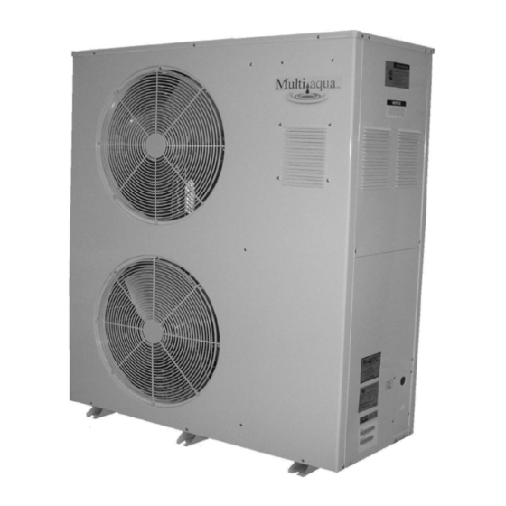
- Page 3 Heat Pump Air Cooled Liquid Chiller Size Range: 5 Tons Multiaqua Model Number: MACH-060-1 Part 1 — General 1.01 SYSTEM DESCRIPTION Multiaqua air cooled liquid heat pump chiller are designed using a scroll compressor, low sound condenser fans and a high efficiency pump.
- Page 4 F. Pump: 1. Circulating pump shall be stainless steel with high efficiency enclosed motor. 2. Unit shall have chilled liquid solution piping to the exterior of the cabinet. 3. Shall have a max working pressure of 60 psig. G. Evaporator: 1.
- Page 5 4.02 Electrical Requirements A. Primary electrical power supply shall enter the unit at a single point. B. Electrical power supply shall be rated to withstand 120°F operating ambient temperature. C. Unit shall be available in 208/230-01-50/60. D. Control points shall be accessed through a terminal block.
- Page 6 MACH-060 Product Specifications Physical Data Coil Chiller Weight (lbs) Model Copper Height Length Coil Height Length Width Refrigerant Number Diameter Shipping (in) (in) Rows (in) (in) (in) R407c (in) MACH060 49.75 39.75 16.25 92.95 oz Electrical Data Condenser Fuse or HACR Circuit Compressor Fan Motor Pump Motor...
- Page 7 MACH-060 Product Specifications MACH-060 Capacity / Watts / EER MACH060 COOLING MACH060 HEATING O/A Temp (°F) O/A Temp (°F) Tons Tons 11.55 3.19 8.32 9.97 3.68 9.40 9.44 4.25 10.63 8.81 4.79 11.98 8.68 5.32 13.03 Notes: Cooling is based on 44°F leaving water temperature. Heating is based on 130°F leaving water temperature Glycol Solution Data Propylene Glycol % Min.
- Page 8 MACH060 Cooling Performance Data MACH060 CAPACITIES with 0% Glycol ENTERING AIR TEMPERATURE (°F) LWT (°F) TONS GPM TONS GPM TONS GPM TONS GPM TONS GPM 3.90 3.70 3.60 3.50 3.50 4.50 4.30 4.20 4.10 4.10 4.80 4.60 4.50 4.30 4.40 5.10 4.90 4.80...
- Page 9 MACH060 Cooling Performance Data MACH060 CAPACITIES with 30% Glycol ENTERING AIR TEMPERATURE (°F) LWT (°F) TONS GPM TONS GPM TONS GPM TONS GPM TONS GPM 3.82 3.63 3.53 3.43 3.43 4.41 4.21 4.12 4.02 4.02 4.70 4.51 4.41 4.21 4.31 5.00 4.80 4.70...
- Page 10 MACH060 Heating Performance Data MACH060 CAPACITIES with 0% Glycol ENTERING AIR TEMPERATURE (°F) LWT (°F) TONS GPM TONS GPM TONS GPM TONS GPM TONS GPM 3.19 3.68 4.25 4.79 5.32 MACH060 CAPACITIES with 10% Glycol ENTERING AIR TEMPERATURE (°F) LWT (°F) TONS GPM TONS GPM TONS GPM TONS GPM TONS GPM 3.16 3.64...
- Page 11 MACH060 Heat Pump Chiller Pump Curve Pump Model Numbers SSP-1 = 208/230-1-50/60 SSP-2 = 208/230/460-3-50/60 0.5 Horsepower...
-
Page 13: Table Of Contents
Table of Contents Page Introduction System Description & Sequence of Operation Electrical & Physical Data Service Clearances Description of Electrical Controls Chiller Controls Sequence of Operation Refrigeration System Operation Description of Refrigeration Components Piping System Components Layout & Design Banked Chiller Configuration Installation Notes Propylene Glycol Content Expansion Tank... -
Page 14: Introduction
Multiaqua Heat Pump Chiller Manual The Multiaqua Chiller System is the only air conditioning/refrigeration system of its kind in the world today offering the degree of application flexibility described in the following manual. The Multiaqua Chiller System is not only unique in its application flexibility; it is unique in superior quality, rated capacity and rugged durability. -
Page 15: System Description & Sequence Of Operation
System Description & Sequence of Operation The Multiaqua MACH (Multiaqua Air Conditioning Heat Pump) is self-contained Reverse Cycle Chiller featuring dual condenser fans, direct expansion outdoor coil (air side) and a brazed plate liquid solution heat exchanger (liquid side). The outdoor coil acts as a condenser expelling heat from the refrigeration process in cooling and is an evaporator coil in the reverse cycle heat pump mode. - Page 16 It must be recognized that ferrous pipe may cause accelerated deterioration of the brazed plate heat exchanger and could void the heat exchanger warranty. *Also Included in this manual is a piping section that includes piping system design, installation and balancing. Equipment sizing for a Multiaqua solution system can utilize Load Diversity.
-
Page 17: Electrical & Physical Data
ELECTRICAL AND PHYSICAL DATA The information contained in this manual has been prepared to assist in the proper installation, operation and maintenance of the chiller. Improper installation, or installation not made in accordance with these instructions can result in unsatisfactory operation and/or dangerous conditions and can cause the related warranty not to apply. -
Page 18: Service Clearances
Consult local building codes or ordinances for special installation requirements. When selecting a site to locate the chiller, consider the following: • A minimum clearance of 60” on the front fan discharge, 12” on the rear air inlet and a 24” clearance is required on the service side. -
Page 19: Description Of Electrical Controls
Description of Electrical Controls Control Transformer: The control transformer is rated at 24 vac, 40 va (1.6 amps @ 24vac) Pump Bypass Timer: The pump bypass timer is a 24 vac, 3-wire control. When energized the timer will bypass the flow switch for 10 seconds (by creating a circuit to the pump relay), energizing the pump relay, allowing the pump to operate long enough to close the flow switch. - Page 20 Description of Electrical Controls (continued) The low-pressure switch is an automatic reset control Low Pressure Switch: that senses compressor suction line pressure. It opens at 40 PSIG and closes at 80 PSIG. Flow Switch: The flow switch senses liquid solution flow. The paddle of the switch is inserted through a fitting into the pump discharge line.
- Page 21 Description of Electrical Controls (continued) Liquid Solution Temperature ControlThe liquid solution temperature control is an adjustable microprocessor based temperature control. This control receives temperature information from a thermistor located on the liquid solution supply line. A liquid crystal display continually indicates liquid solution temperature. The control is mounted inside the chiller cabinet.
-
Page 22: Chiller Controls Sequence Of Operation
Chiller Controls Sequence of Operation *The paragraphs below will outline the common sequence of operation for the MACH then expand into the operation sequence for both the water heating and water chilling modes of operation. Following this information will be a section on system faults and problems solving. The pump will not self-prime. - Page 23 he chiller/heat pump when operating in the heating mode utilizes the outdoor coil as an evaporator. The evaporator (outdoor coil) in heating must be 20° or more below the outdoor ambient temperature. This means that on a 30° day the coil temperature will be at a 10° or below operating temperature. Operating in this temperature range causes frost to form on the outdoor coil surfaces, which cut down on the heating efficiency and capacity (BTUH).
-
Page 24: Refrigeration System Operation
SYSTEM FAULTS: Flow Switch Opening: The flow switch is normally closed during pump operation. Should liquid solution flow be interrupted for any reason the control will open, shutting down and locking out system operation. The only exception to this is when power is first applied to the unit, and the pump bypass timer bypasses the flow switch for 10 seconds. If flow is less than 3 GPM flow switch will not close. -
Page 25: Description Of Refrigeration Components
Description of Refrigerant Components Scroll Compressor: Scroll technology ensures reliable high efficiency. All Multiaqua units feature Scroll performance at a low sound level over a wide range of operating conditions. Caution must be used when near the top of the Scroll compressor. Operating temperatures can be high enough to cause serious Injury. -
Page 26: Piping System Components
Description Of Refrigerant Components (Continued) Condenser coil: The air-cooled condenser coil is of copper tube with aluminum fin construction. The coil is protected by a painted metal condenser grille. Piping System Components Supply Storage Tank: The Supply Storage Tank must be used in systems with less than 25 gallons of liquid solution. -
Page 27: Layout & Design
Piping System Components (Continued) Motorized Control Valve: The fan coil's motorized valve controls the flow of liquid solution to the system coil. Each fan coil in the system should have a motorize valve. Part Number: MZV524E-T 1/2" 2-Way Zone Valve MZV525E-T 3/4"... -
Page 28: Banked Chiller Configuration
Banked Chiller Configuration 1. Ball Valve 2. Wye Strainer 3. Pressure Indicator 4. Temperature Indicator 5. Chiller 6. Expansion Tank 7. Storage Tank Notes: Installing Multiaqua chillers in parallel is recommended. An adjustable valve must be used to throttle the discharge liquid solution flow rate to appropriate levels based on capacity and glycol mix percentages. -
Page 29: Installation Notes
Installation Notes: Piping such as PEX, steel, copper or PVC can be used with the Multiaqua system. Check local building codes for material conformation. Care must be taken when using PVC as the presence of propylene glycol may destroy plastics. Pressure drop data for the selected piping material is readily available and should be used. -
Page 30: Propylene Glycol Content
Installation Notes: (Continued) Ethylene Glycol is environmentally hazardous and not recommended. Inhibited Propylene Glycol ( typical automotive coolant) is not to be used in a Multiaqua Chiller under any circumstances. Dow Chemical's "Ambitrol" family of Glycol-based coolants of food grade Propylene Glycol is suggested. Information on Ambitrol is available from Dow at www.dow.com, search word "Ambitrol". -
Page 31: Filling The System With Propylene Glycol
Filling System with Liquid Solution and Coolant (Propylene Glycol) Concentrations of Propylene Glycol in excess of 50% will destroy o-rings in fittings and pump. Water shoul be added to the system first or a liquid solution diluted Propylene Glycol mix. Before filling system with Propylene Glycol and water, pressure test the piping system with compressed air. -
Page 32: Liquid Solution Balancing
Liquid Solution Balancing: Liquid solution balancing will require an accurate digital thermometer to measure return line liquid solution temperature at each air handler. Set the chilled liquid solution temperature control in the chiller at a normal operational temperature (44°F) and measure pump discharge temperature with the digital thermometer to check system solution temperature. -
Page 33: Wiring Diagrams
MACH060-01 Wiring Diagram 208/230-1-50/60... - Page 34 MACH060-01 with Low Ambient Kit Wiring Diagram 208/230-1-50/60...
Need help?
Do you have a question about the MACH-060-1 and is the answer not in the manual?
Questions and answers