
Related Manuals for Warner PC-505B

Summary of Contents for Warner PC-505B
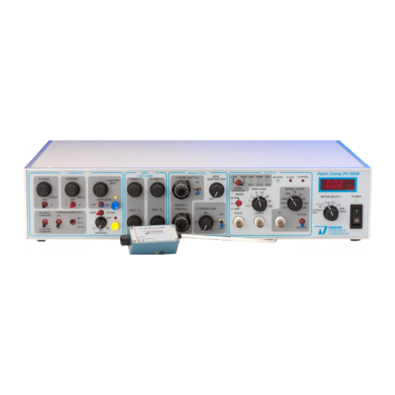
- Page 1 PC-505B Manual, Rev. 201013 Warner Instruments Whole Cell/Patch Clamp Amplifier Model PC-505B Warner Instruments 1125 Dixwell Avenue, Hamden, CT 06514 (800) 232-2380 / (800) 547-6766 - support www.warneronline.com...
-
Page 2: Table Of Contents
PC-505B Manual, Rev. 201013 Table of Contents INTRODUCTION ............................4 NOMENCLATURE ............................ 6 Text conventions ............................. 6 Device panel abbreviations ........................6 Signal polarity conventions ........................6 Membrane current (I ) ......................... 6 Membrane potential (Vm) ........................7 CONTROL DESCRIPTION ........................8 Front panel .............................. - Page 3 PC-505B Manual, Rev. 201013 Cap Comp checkout..........................24 Current clamp checkout ........................24 OPERATION ............................26 Initial settings ............................26 Preliminary ............................27 Mount the electrode ..........................27 Submerge the electrode tip ......................... 27 Zero the pipette offset ......................... 27 Measure the pipette resistance (RP)....................
-
Page 4: Introduction
PC-505B Manual, Rev. 201013 Recommended reading ......................... 44 Glossary ..............................47... - Page 5 PC-505B Manual, Rev. 201013 The PC-505B Whole Cell/Patch Clamp Amplifier is a low noise, resistive-feedback patch clamp designed for whole-cell, single channel, and bilayer applications. The unique circuitry and dedicated design of this amplifier allows Warner Instruments to present a superior quality instrument at a cost significantly below that of many of our competitors.
-
Page 6: Nomenclature
Any other formatting should be apparent from context. Device panel abbreviations Many controls on the PC-505B have abbreviations associated with them. Several of these abbreviations are listed here for quick reference. In addition, these and other terms have been collected and are included in a Glossary at the back of this manual. -
Page 7: Membrane Potential (Vm)
PC-505B Manual, Rev. 201013 outside-out patch and whole cell preparations, this corresponds to the conventional physiological definition of outward transmembrane current. With inside-out or cell-attached patches, the physiological transmembrane current equals minus the indicated I Membrane potential (Vm) Membrane potential is defined as pipet potential minus bath potential. With outside- out patch and whole cell preparations, this corresponds to the conventional physiological definition of transmembrane potential. -
Page 8: Control Description
PC-505B Manual, Rev. 201013 CONTROL DESCRIPTION The instrument front panel is divided into several control blocks. Controls within these blocks are dedicated towards a common functional purpose. Each control block is outlined in blue and is clearly labeled as , and . - Page 9 When internal command is selected and is switched on, a 1V p-p COMMAND SENSITIVITY square wave test pulse (line frequency; 50/60 Hz) is generated by the PC-505B. The test pulse is attenuated by the toggle and is available for adjustment of...
-
Page 10: Fast Cap Comp (Fast Capacitance Compensation) Command Block
PC-505B Manual, Rev. 201013 function generates an internal +1.5 V pulse which is applied to the headstage. The pulse duration may be adjusted from 0.1 to 10 ms as indicated. A safe/active toggle switch arms the circuitry and the pulse is initiated when the button is depressed. -
Page 11: Output Command Block
PC-505B Manual, Rev. 201013 Series R Series resistance compensation is used to compensate for the voltage drop across the electrode and access resistance in the experimental setup. This control is used to adjust the time constant of the – control facilitating measurement of membrane resistance which SLOW can be read from the dial. - Page 12 BYPASS two BNC outputs labeled I located at both the front and rear panels. Voltammetry The PC-505B can be used as a potentiostat for voltammetric measurements. A rear panel increases maximum output of the control (in the POTENTIOSTAT SWITCH VOLTAGE HOLD block) to ±...
-
Page 13: Meter Section
(with open input and properly shielded from 60 Hz interference) is approximately 0.040 pA. Full scale range is 1.999 pA RMS. Front and rear panel BNC’s and connectors The PC-505B has input and/or output BNC’s on both front and read panels. These include I and V... - Page 14 PC-505B Manual, Rev. 201013 x10 – Output BNC reporting the transmembrane potential (active only in current clamp mode). – Output BNC reporting membrane current in both voltage and current clamp modes. Rear panel BNC’s – Output BNC reporting membrane current when instrument is in voltage clamp mode, and V x10 when instrument is in current clamp mode.
- Page 15 PC-505B Manual, Rev. 201013 – Output BNC reporting the filter setting in use. Telegraphs range from FILTER TELEGRAPH 0.2 to 2.0 V in 0.2 V steps as shown below. Filter telegraph settings Frequency (Hz) telegraph out (V) Bypass – Sync out provides a TTL pulsed output for synchronizing an oscilloscopes or...
-
Page 16: Headstage
PC-505B Manual, Rev. 201013 Grounds – Circuit and chassis ground connectors (black and green, respectively) are binding posts supplied with a shorting link. For most recording situations, the shorting link can remain connected with no detrimental effect in amplifier performance. However, there are occasions where line noise can be reduced if the two grounds are isolated from each other. -
Page 17: Model Cell
PC-505B Manual, Rev. 201013 Holders are machined from polycarbonate to minimize electrical noise and are custom bored to accommodate various diameter pipet electrode glasses. The micropipet is secured with a rubber gasket and a polycarbonate screw–cap matching the OD of the pipet glass. A 1 mm pin makes electrical contact with the silver wire and plugs the holder onto the headstage. -
Page 18: Setup And Initial Test
Power line voltage requirements for the PC-505B are specified on the serial number nameplate attached to the chassis rear. They are wired for either 100-130 VAC or 220-240 VAC at either 50 or 60 Hz. Check to be sure the PC-505B is wired for the line voltage and frequency to be used. -
Page 19: Headstage Preparation
The headstage probe normally requires a grounded enclosure (Faraday cage) to shield it from 50/60 Hz line interference. The shield should be grounded to the (black) circuit ground jack on the rear of the PC-505B chassis. Place the headstage into the shield enclosure and run the grounding cable to the amplifier in the same bundle as the headstage cable. - Page 20 PC-505B Manual, Rev. 201013 Begin each checkout section by returning the PC-505B to this known configuration. Headstage inputs: Open Front panel controls: Control Control block Initial setting POWER METER fully CCW, toggle switch off VOLTAGE HOLD COMMANDS fully CCW, toggle switch off...
-
Page 21: Rms Noise Checkout
PC-505B Manual, Rev. 201013 RMS noise checkout Set the switch to the RMS noise position. METER SELECT Check for a noise reading on the at or below 0.038 pA. If the value reported is METER high, then relocate or adjust the headstage and shielding to minimize noise inputs. -
Page 22: External Dc Voltage Command Checkout
PC-505B Manual, Rev. 201013 Verify that scope reads 10 times the panel reading (2 div at these settings). METER Using control adjust to 0 mV. JUNCTION ZERO METER Set the switch to the Vc position. Verify that reads zero. -
Page 23: Internal Ac Voltage Command Checkout
PC-505B Manual, Rev. 201013 13. Set oscilloscope to 5 mV/div. 14. Verify that reads 1 mV and that oscilloscope reads 10 mV (2 div at these settings). METER 15. Return amplifier to initial settings. Internal AC voltage command checkout block) to internal command. -
Page 24: Cap Comp Checkout
PC-505B Manual, Rev. 201013 10. Set to 10 mV/pA. GAIN 11. Verify that oscilloscope reads +1 V (1 div at these settings) 12. Set to negative (–). VOLTAGE HOLD 13. Verify that reads –10 pA. METER 14. Verify that oscilloscope reads –1 V (1 div at these settings) 15. - Page 25 PC-505B Manual, Rev. 201013 to V METER SELECT toggle to positive (+) CURRENT HOLD Adjust control until reads 50 mV. CURRENT HOLD METER to V METER SELECT Verify that reads 0 mV. (e.g. command is disabled in I mode.) METER CURRENT HOLD 10.
-
Page 26: Operation
PC-505B Manual, Rev. 201013 OPERATION Initial settings This section assumes that the following items are in place: • • data acquisition system or prepared patch pipettes (capillaries) • oscilloscope electrode holder with flexible tubing • air table / Faraday cage attached to the side port •... -
Page 27: Preliminary
PC-505B Manual, Rev. 201013 Preliminary Mount the electrode Position the Ag-AgCl reference electrode or KCl-agar salt bridge into the recording chamber and connect to the ground pin on the headstage case. NOTE: If using a Ag/AgCl wire or pellet reference electrode, make sure that your Ag wire/pellet is fully chlorided. -
Page 28: Measure The Pipette Resistance (Rp)
PC-505B Manual, Rev. 201013 To establish a zero baseline reference potential, activate the junction zero circuit by placing the toggle switch into the on position. This turns the auto-zero LED on. AUTO ZERO Next, depress and hold the to activate the automatic correction... -
Page 29: Voltage Clamp
PC-505B Manual, Rev. 201013 wave to the pipette. Adjust your acquisition system or oscilloscope and amplifier so as to clearly display 1-2 complete cycles of the output current signal. An example trace is shown to the right. Note: If needed, the amplitude of the... -
Page 30: Set Electrode Capacitance Compensation
PC-505B Manual, Rev. 201013 3. If a seal doesn’t form within about 5-10 min, it probably will not. Take a new pipette and start again. 4. Never attempt to clean and re-use a used pipette. It will never make a seal. -
Page 31: Patch Or Whole Cell Recording
PC-505B Manual, Rev. 201013 current on the oscilloscope. An example is shown on the previous page. Since the test pulse has a known voltage amplitude (100 mV in this case), you can calculate RS by use of Ohm's law (R=V/I). A good gigaseal resistance is typically in the range 1-10 G. -
Page 32: Patch Recording - Cell-Attached Patch
The PC-505B controls can be set to values needed to perform your work. However, some controls should not be moved or measurement artifacts or patch rupture can occur. These are shown in the table below. -
Page 33: Whole-Cell Recording - Series R Compensation
PC-505B Manual, Rev. 201013 Rupture is signaled by a sudden large increase in current when in voltage clamp mode, TEST PULSE or as a sudden decrease in voltage at the TEST PULSE x10 terminal when in current clamp mode. Once... -
Page 34: Whole-Cell Recording - % Correction
PC-505B Manual, Rev. 201013 • Return to and adjust the overshoot SERIES R away. Go back and forth between the SLOW controls until you’ve completely SERIES R removed the leading spike and made the leading corner as sharp as possible. An example is shown to the right. -
Page 35: Current Clamp
PC-505B Manual, Rev. 201013 Current clamp Current clamping is used mainly with whole-cell recording. In current clamp mode, the , and controls are inactive. VOLTAGE HOLD JUNCTION ZERO AUTO ZERO CAP COMP CURRENT HOLD becomes active, as well as the V x10 output. -
Page 36: External Command Currents
Warner has a complete Bilayer Workstation available, and if needed, the amplifier used with that system can be replaced with the PC-505B. Regardless if you’re using the PC-505B with Warner’s Bilayer Workstation or with a custom rig, Plug the HB-205B headstage into the... -
Page 37: Theoretical Considerations
1-10 min. Rinse well with tap water, then with distilled. Electrode holders The standard holder used with PC-505B are the QSW-AxxP straight body style (purchased separately). These holders use a 0.010" diameter, 99.99% pure silver wire to couple the signal from the micropipet solution to the input pin of the headstage amplifier. -
Page 38: Care And Use Of Holders
PC-505B Manual, Rev. 201013 holder wire must be plated with chloride (AgCl) to within 2-3 mm of the end cap which secures the micropipet. A 2 mm OD port on the side of these holders are used for applying pressure or suction through standard 1/16"... -
Page 39: Reference Electrodes
A reference electrode in the recording chamber maintains the bath at circuit ground potential, the reference potential for all measurements. It is also the return path for currents from the pipet electrode. A variety of Ag-AgCl reference electrodes are available from Warner Instruments. -
Page 40: Appendix
PC-505B Manual, Rev. 201013 APPENDIX Specifications HEADSTAGES LC-201B Headstage single channel currents to 200 pA (50 G/500 ) whole cell currents to 20 nA. HC-202B Headstage single channel currents to 200 pA (50 G/50 ) whole cell currents to 200 nA... - Page 41 PC-505B Manual, Rev. 201013 FRONT PANEL OUTPUTS I m (membrane current) gains of 0.05 to 10 mV/pA with 50 headstage resistor gains of 0.5 to 100 mV/pA with 500 headstage resistor gains of 5 to 1000 mV/pA with 50 G headstage resistor...
-
Page 42: Accessories And Replacement Parts
PC-505B Manual, Rev. 201013 Accessories and replacement parts Model Number Order Number Description Headstages: When ordering additional or replacement headstages, please reference the serial number of your PC-505B. LC-201 64-0004 50 G/500 M feedback resistors HC-202 64-0005 50 G/50 M feedback resistors... -
Page 43: Warranty And Service
Warranty The model PC-505B is covered by our Warranty to be free from defects in materials and workmanship for a period of three years from the date of shipment. If a failure occurs within this period, we will either repair or replace the faulty component(s). - Page 44 PC-505B Manual, Rev. 201013 IMPORTANT: CUSTOMERS OUTSIDE OF THE U.S. Please be sure to contact us before return shipping any goods. We will provide instructions so that the shipment will not be delayed or subject to unnecessary expense in clearing U.S.
- Page 45 PC-505B Manual, Rev. 201013 Certifications Declaration of Conformity CE MARKING (EMC) Application of Council Directive: 89/336/EEC Standards To Which Conformity EN55022 Class A Is Declared: EN61000-3-2 EN61000-3-3 EN50082-1:1992 EN61000-4-2 EN61000-4-3 ENV50204 EN610000-4-4 EN610000-4-8 EN610000-4-11 Manufacturer’s Name: Warner Instruments, LLC Manufacturer’s Address:...
- Page 46 PC-505B Manual, Rev. 201013 Declaration of Conformity CE MARKING (LVD) Application of Council Directive: 73/23/EEC Standards To Which Conformity Is EN61010-1:1993 Declared: Manufacturer’s Name: Warner Instruments, LLC Manufacturer’s Address: 1125 Dixwell Avenue Hamden, CT 06514 Tel: (203) 776-0664 Instrument Amplifier...
- Page 47 PC-505B Manual, Rev. 201013 Warner Instruments A Harvard Apparatus Company...
- Page 48 PC-505B Manual, Rev. 201013 Glossary A/D converter – Analog to Digital converter. Computers are inherently digital while the voltage or current output from an amplifier is analog. Therefore, a signal must be first converted to a digitized form before a computer or its software can accept it. Desirable features in an A/D converter include rapid signal conversion, small-step resolution and low noise.
- Page 49 PC-505B Manual, Rev. 201013 current-voltage relationship – A measure of the way in which the current varies as a function of the applied voltage. In an Ohmic device (obeys Ohm’s law or V=IR), this relationship is linear. An understanding of the current-voltage relationship of a channel yields information about that channel’s function.
- Page 50 PC-505B Manual, Rev. 201013 junction potential – A difference in conductivity between two dissimilar materials will appear as a small voltage when the two materials are brought into contact. This voltage is termed the junction potential. LED – Light Emitting Diode. The red, green or yellow lighted indicators on the front of many devices. LED’s are preferred indicator light sources due to their low power consumption.
- Page 51 PC-505B Manual, Rev. 201013 TTL – Transistor, Transistor Logic. Voltage ranges used to define an on or off state in binary devices. 0-0.8 V defines a logic 0 state and 2.4-5.0 V defines a logic 1 state. unitary channel conductance – A measure of the ability of a channel to pass an ion from one side of the membrane to the other.
Need help?
Do you have a question about the PC-505B and is the answer not in the manual?
Questions and answers