Table of Contents
Advertisement
Quick Links
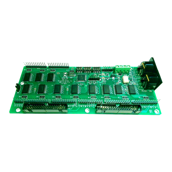
MIPC-1A 64 INPUT TO MIDI ENCODER
Features
64 inputs, no matrix wiring.
DIP switch selectable, Keyboard inputs with starting midi note 35, Stop Input with midi note starting at 0.
In Stop Input Mode, switch selectable midi note range 0 to 63 or 64 to 128.
In Keyboard or Stop input mode, an additional 24 Piston Inputs are available.
DIP Switch selection of Midi Channels 1 to 16.
4 Analog Inputs for Swell Shoes and Crescendo.
Crystal Controlled Microprocessor.
Midi In And Midi Out Jacks. Optical coupled MIDI INPUT.
Operating voltage, 8 to 15 Volts DC at less then 10ma current..
Input connections either by two 34 pin ribbon cables or 5 twelve Molex KK-100 series connectors, plus 1 4
pin connector for inputs 61 to 64. Contact commons are wired to GROUND.
Installation
Switch Settings, refer to Fig. 1
DIP SW3 Keyboard/Stop Mode, locate the THREE position DIP switch marked SW3-1, SW3-2 and SW3-3. If the card is
being used for Manual (keyboard) or Pedal inputs, set SW3-1 to OFF. In the Manual mode, the starting midi note for input 1
(C1) is NOTE 36. The same applies to Pedal Board wiring.
For the STOP Mode, set SW3-1 to ON, the first midi note for input 1(C1) is Note 0 and follows through to midi note 63 for In-
put terminal 64. Setting SW3-2 to the ON position will change Input 1 (C1) to midi note 64 and follow through to midi note 127
on Input Terminal 64. This option will allow up to 128 Stops on one Midi Channel.
SW3-3 will ENABLE the 24 AUX inputs when SW3-3 is set to ON or DISABLE with SW3-3 set to OFF. In the Disable (OFF)
mode, the input are off in both the Keyboard and Stop mode.
DIP SW2 MIDI CHANNEL SELECTION, Locate the Midi Channel Selection, four position DIP switch and refer to Fig. 2,
the MIDI Channel Switch Setting. The X indicates the that switch is set to ON position. Channels 1 through 16 can be selected
for each card. The recommended channels assignments are the following. Pedals-Channel 1, Keyboard 1-Channel 2, Keyboard
2-Channel 3, Keyboard 3- Channel 4. Stops and Pistons-Channels 15 and 16. These are only recommendations and seem to be
the normal channel assignments that have been followed in midi files that were created in Hauptwerk.
DIP SW1 SWELL SHOE, The 4 position Swell Shoe DIP switch is Factory set to ON and should be left ON if not used. Tun-
ing any of the four switch's to OFF with no swell shoe pot connected will result is a stream of midi data. Swell shoe connections
will be covered later.
Wiring, See Page 4 for additional information for the MIPC-1A-HV version.
64 Inputs, connections to the 64 inputs can be made one of two ways depending on connector configuration when the card was
ordered. For the two ribbon connectors, standard flat 34 conductor ribbon cable would be used with connectors crimped on one
or both ends. The 12 pin Molex KK-100 connectors and crimp terminals can accept wire sizes from 22 to 26 gage.
Contact Common All contact common terminals for the manuals, pedals and stops should be connect to Ground or 0 volts. The
inputs on the card are at Plus 5 volts and need to be pulled to Ground to operate.
Additional 24 Inputs. These input terminals are separate form the 64 inputs and can be used for stops or pistons. When DIP
SWITCH SW3-1 is set of OFF, the KEYBOARD Mode, midi notes 104 to 127 will be generated and on the same midi channel
that MIDI CHANNEL Switch SW2 is set to.
Setting DIP SW3-1 to the ON or STOP position will cause the 24 output to generated midi notes 0-23 and 64 to 87, depending
For Hauptwerk
1
Advertisement
Table of Contents

Summary of Contents for DesignTech MIPC-1A
- Page 1 OFF with no swell shoe pot connected will result is a stream of midi data. Swell shoe connections will be covered later. Wiring, See Page 4 for additional information for the MIPC-1A-HV version. ...
- Page 2 Power Connections. The MIPC-1A card has power connection block with four terminals, two for the PLUS power line and two for the GROUND power line. The two terminals configuration is designed to provide a terminal for the incoming power wire and a second terminal for the out going wire to the next card in the series.
- Page 3 DIP SW-2, MIDI CHANNEL SELECT DIP SW-3, SW-1= Manual/Stop Select. Off=Manaul, ON= Stop Select THE MIPC-1A. ONLY A COMMON GND DIP SW3, SW-2= MIDI NOTE RANGE SELECT IN STOP MODE. OFF= 0-63, ON=64-128 DIP SW3, SW3-3 AUX 24 INPUTS ENABLE/DISABLE. OFF=DIABLE , ON=ENABLE PISTONS AUX 24 INPUTS.
- Page 4 MIPC-1A-HV KEY AND PISTON SWITCH INPUTS PISTONS AUX 24 INPUTS. Input 1 DIP SW 3 DIP SW 3 Input 24 MIDI IN MIDI OUT MIDI IN MIDI OUT AUX 24 ENABLE SW3-1 SW3-1 SW3-2 MIDI NOTE RANGE SW3-2 SW3-3 SW3-3...
- Page 5 22K (22,000 ohm) resister to the each input terminal. The resister can be added either at the card pin or stop action switch. Failure to add a 22k resistor to each used input pin can result in damage to the MIPC-1A-HV circuit.
- Page 6 Positive/ Negative Input Jumper The jumper located at the end of the MIPC-1A and MIPC-1A-HV needs to be set in one of two positions for proper operations. If the jumper is not present, the encoder will not operate correctly.
- Page 7 The items can be returned for a full refund within 3 days if it has not been damaged or misused after delivery. Except as provided herein, DesignTech Systems, Inc makes no warranties, expressed or implied, including warranties or merchantability and fitness for a particular purpose.
Need help?
Do you have a question about the MIPC-1A and is the answer not in the manual?
Questions and answers