
Related Manuals for Vorsis AP3

Summary of Contents for Vorsis AP3
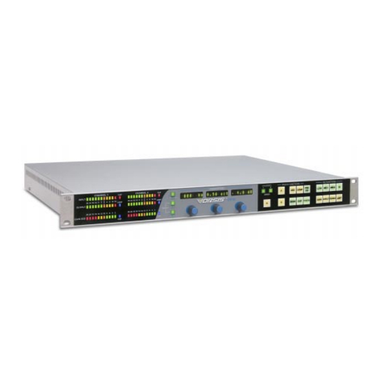
- Page 1 AP3 Digital Signal Processor TECHNICAL MANUAL (+,", ™ 600 Industrial Drive, New Bern, North Carolina, USA 28562...
- Page 2 AP3 Digital Signal Processor Technical Manual - 2nd Edition AP3 Digital Signal Processor Technical Manual - 2nd Edition AP3 Digital Signal Processor Technical Manual - 2nd Edition AP3 Digital Signal Processor Technical Manual - 2nd Edition AP3 Digital Signal Processor Technical Manual - 2nd Edition ©2006 Vorsis...
-
Page 3: Table Of Contents
Expander ........................2-4 Equalization ................... 2-5 Parametric Equalizer ....................2-5 Dynamics ..................2-5 Multiband Compressor - “Production” ..............2-5 Multiband Limiter - “Airchain” ..................2-5 AGC .......................... 2-6 Limiter ........................2-6 Metering ..................2-6 page Contents – 1 AP3 / Jan 2006... - Page 4 Inputs Follow Presets/Input Stay Same ..............2-10 Sample Rate ......................2-10 IP Address ....................... 2-11 Subnet/Gateway ...................... 2-12 AP3 Front Panel Control Functions (Table 1-Table 3) ....2-13 Chapter 3 - Vorsis AP3 GUI Getting Started ................3-3 Connecting the AP3 and the GUI ..........3-3 Using the GUI ................3-4...
- Page 5 Schematic ....................... 4-2 Load Sheet ......................4-5 Processor Switch Card (PSW-1) Load Sheet ......................4-6 Appendices Appendix 1 Using the AP3 ................A-3 Five-Minute Processor .................... A-3 About Listening ....................... A-4 Appendix 2 Parameters, Units and Ranges ..........A-6 Appendix 3 Replacement Parts List ............
- Page 6 Unbalanced Analog Connections ................1-8 Unbalanced Digital Connections (SPDIF) .............. 1-8 XLR/RJ-45 Inputs Pinout Drawing................1-9 DB-25 Inputs/Outputs Pinout Drawing ..............1-10 XLR/RJ-45 Outputs Pinouts Drawing ..............1-11 RJ-45/DB-9 Control/Ethernet/GPI Pinouts Drawing..........1-12 page 1 – 1 AP3 / Apr 2005...
-
Page 7: Introduction
AC mains. Note: To de-energize the Vorsis™ AP3, unplug its AC cord from the AC mains. page 1 – 2... -
Page 8: I/O Connections
AP3 to be used in an existing digital system. AES sources are by design stereo; if the AP3 is not set to be stereo the appropriate Left or Right signal within the AES stream will be applied to the signal path. -
Page 9: Outputs
Pin 3 – AES IN LO Outputs The AP3’s two output signals are available as individual line level analog (+4dBu, balanced) on the two male XLR ANALOG OUT connectors, and in digital AES formatted on a male XLR connector, paralleled by an RJ-45 connector for CAT5 connection. These analog and digital outputs are available also on the DB-25 connector. -
Page 10: Control Ports
NOTE: The remote mic controls are meant to be used when the AP3 is processing two separate mono signals, typically microphones (see “Selecting a Signal Path” on pages 2-7 to 2-8). If the AP3 is in “stereo” mode there will be some non-intuitive interaction between the two sets of remote mic controls. -
Page 11: On And Off Tallies
Presets 1-8. For example, a 5VDC signal applied between Pin 1 (GPI Com) and Pin 6 (GPI 1 In), will take the AP3 preset stored in location PRE #001. The + (plus) side of the 5V signal is applied to the active selector pin (Pin 6 in the example) and the - (minus) side of the 5V signal is applied to GPI Com, Pin 1. -
Page 12: Ethernet Interface
G E N E R A L I N F O R M A T I O N Ethernet Interface Networked systems are connected to the AP3 via straight (pin to pin) CAT5 cable. For typical CAT5 cable pinouts see below. These connections are for communicating with the configuration computer, via a network. -
Page 13: Digital Audio Connections
(like Belden 9451), just as if you were connecting a balanced source. At the unbalanced source machine’s output, connect the + output to the HI input wire and connect the source machine GND wire to LO. Connect the shield at the AP3 end only. - Page 14 PIN 1 XLR SH - AES IN SH PIN 2 XLR HI - AES IN HI XLR-F PIN 3 XLR LO - AES IN LO AES IN HI RJ-45 AES IN LO page 1 – 9 AP3 / Apr 2005...
- Page 15 LINE 1 OUT HI LINE 2 OUT SH LINE 2 OUT LO LINE 2 OUT HI AES IN SH AES IN LO AES IN HI AES OUT SH AES OUT LO AES OUT HI page 1 – 10 AP3 / Apr 2005...
- Page 16 PIN 1 XLR SH - AES OUT SH XLR-M PIN 2 XLR HI - AES OUT HI PIN 3 XLR LO - AES OUT LO AES OUT HI RJ-45 AES OUT LO page 1 – 11 AP3 / Apr 2005...
- Page 17 RXD + GPI 8 IN GPI 7 IN GPI 6 IN GPI 5 IN RJ-45 GPI 4 IN DB-9 RXD - GPI 3 IN GPI 2 IN GPI 1 IN GPI COM page 1 – 12 AP3 / Apr 2005...
- Page 18 New Password ......................2-10 Access ........................2-10 Inputs Follow Presets/Input Stay Same ..............2-10 Sample Rate ......................2-10 IP Address ....................... 2-11 Subnet/Gateway ...................... 2-12 AP3 Front Panel Control Functions (Table 1-Table 3) ....2-13 page 2 – 1 AP3 / Jan 2006...
-
Page 19: Selecting A Signal Path
AP3 signal paths is being operated upon - the appropriate path’s button will be lit; pressing the other button will cause it to be lit instead, and command and display now act on that path. The AP3 can be made “stereo” (i.e. both paths being controlled together) by simultaneously holding down both Channel 1 and 2 buttons for two seconds;... -
Page 20: Basic Setup
AES Clock Error Messages - will flash obnoxiously if the Sample Rate is set to AUTO and no AES input is connected or if your AES source and the AP3 don’t agree on a sample rate. See the AES Error Messages section (page 2-11) to decipher these. -
Page 21: Expander
TELCO circuit. Such uses become more necessary if the signal is later subjected to high degrees of compression, either within the AP3 and/or by subse- quent airchain processing - compression tends to make room/breath/ TELCO noises all the more objectionable by raising their level. -
Page 22: Equalization
(Limiting). Multiband Compressor - “Production” The compressor within the AP3 is a multi-band processor. It divides the signal spectrum up into three paths (nominally “LF”, low frequencies, “MF”, mid frequencies, and “HF”, high frequencies) each of which has its own individual compressor, the outputs of which are then recombined. -
Page 23: Agc
AGC elements of the multi-band processor. Limiter Last in the signal processing chain is a precision peak limiter, which is intended to contain the AP3’s output within desired level constraints, most particularly to avoid clipping within or overdriving signal destinations. Metering... -
Page 24: Main Control Group
Presets A Preset is a snapshot of all the AP3’s settings and configuration, with the intention of being able to recall the preset and restore the unit to exactly the same condition at a future juncture. The entire system (i.e. both signal paths, not one signal path at a time) is saved as a preset. -
Page 25: Presets Button
C O N T R O L S A N D F U N C T I O N S over-written. 180 such presets are available. AP3 presets are “sticky” as opposed to “tunable”. What this means is that if an AP3 preset is invoked and adjustments are made, whether by hardware front-panel or by the GUI, those changes do not become part of the preset unless deliberately saved back into it. -
Page 26: Modify
GUI: • Preset order rearrangement while the unit is “live” and in use, and when changing the actual settings of the AP3 would be otherwise unwel- come. • Labeling. We refuse to inflict the simply awful dial-up-a-letter-at-a- time Chinese-water-torture thing on anybody. -
Page 27: New Password
C O N T R O L S A N D F U N C T I O N S New Password Unless the AP3 is fully unlocked (by using the password, if in use) this feature will be inaccessible. -
Page 28: Ip Address
(AUTO/48 or AUTO/44.1). IP Address An AP3 needs telling who it is, from a networking point of view, so that its associated GUI knows how to find it, and what to call it. The device’s IP address is entered in a similar “safe-cracking” manner to the password... -
Page 29: Subnet/Gateway
Entry by dobbying of the last (fourth) number makes the overall an encoder knob. displayed number the IP address by which that AP3 is known to the world. Subnet / Gateway Entered in exactly the same manner as “IPAddres”; these are some- times necessary TCP/IP routing codes. -
Page 30: Ap3 Front Panel Control Functions (Table 1-Table 3)
C O N T R O L S A N D F U N C T I O N S AP3 FRONT PANEL CONTROL FUNCTIONS TABLE 1 PARAMETERS SWITCH PAGE MODE GAIN INPUT GAIN OFFSET (BALANCE) OUTPUT GAIN INPUT M/S or L/R... - Page 31 Inputs Follow Presets or Inputs Stay Same Sample Rate AUTO/48K, AUTO 44.1K, 48K, 44.1K IP Address User defined - 192.168.1.191 default Subnet User defined - 255.255.255.0 default Gateway Not supported - 255.255.255.255 default Not editable page 2 – 14 AP3 / Jan 2006...
- Page 32 V O R S I S A P 3 G U I Vorsis AP3 GUI Chapter Contents Getting Started ................3-3 Connecting the AP3 and the GUI ..........3-3 Using the GUI ................3-4 Dynamic Displays Region ..................3-5 Frequency-Domain Graph ................. 3-5 Bargraph Metering .....................
- Page 33 Q Save ......................3-35 Compare ......................3-35 Bypass ......................3-35 Title Bar Region ....................3-36 Status ....................... 3-36 Devices ......................3-36 Presets ......................3-37 Notes on “Online” and “Offline” working ............... 3-38 page 3 – 2 AP3 / Jan 2006...
-
Page 34: Getting Started
Likewise, the GUI should be installed on the desired PC which is verified to be working correctly with the LAN. It is also possible to work without a LAN by connecting the AP3 and the PC Ethernet ports together using a crossover cable. -
Page 35: Using The Gui
– although not difficult - is beyond the scope of this manual owing to the uniqueness of each situation. Once the AP3 has a valid address, the GUI can find it on the network. Double-click on “Devices” on the GUI; click “Add”; click “Browse” - TIP: If “Trying”... -
Page 36: Dynamic Displays Region
HF gain reductions is drawn. BOTH — This displays a curve of the composite (instantaneously greatest) gain reductions spectrally from both the AGC and the compres- sor. page 3 – 5 AP3 / Jan 2006 AP3 / Jan 2006... -
Page 37: Bargraph Metering
“Channel 1” and “Channel 2” labeling on the starboard) if the AP3 is set up for stereo, or “View A” and “View B” if front of the AP3 unit. operating as two discrete channels. This selects which of the two signal channels within the AP3 is being operated upon / displayed. -
Page 38: Control Area Region
Left-clicking a button gains access to the controls for that portion of the signal-processing. NOTE: The order of EQ and compression can reversed on the AP3 by the condition of “Pre-EQ” selection. This is achieved on the GUI by clicking upon the “SWAP”... -
Page 39: Input
Phase Phase reversal of the signal path, in case there is an inadvertent reversal elsewhere in the signal chain of which the AP3 is a part. Filter High-pass, low-pass filters, and notch. -
Page 40: Expander
V O R S I S A P 3 G U I Expander An expander such as the one in the AP3 (often called a “downward expander”) is a useful tool for re- ducing unwanted background noises. These could be variously... - Page 41 14dB, 20dB tops, is enough to make a signal “disappear” in the context of a mix; the whole gating sound, especially surprisingly its opening, is less obvious with shallower depth. Sometimes the “Surprise!” element is required, though, for effect. page 3 – 10 AP3 / Jan 2006...
-
Page 42: De-Esser
- by ear. Make the “Bandwidth” small, narrow; crank down the threshold (i.e. make it more sensitive), then carefully tune the “Frequency” until the undesired artifact is getting audibly affected. Careful (!) adjustment of “Bandwidth” page 3 – 11 AP3 / Jan 2006... -
Page 43: Emphasis And De-Emphasis
Emphasis and De-Emphasis Emphasis is available at the AP3’s input, and both pre-emphasis and de-emphasis at the output. Emphasis (also known as pre-emphasis, particularly in circumstances... -
Page 44: Transmitter Pre-Emphasis
Since the AP3 has great utility in both FM and AM broadcast paths, a highly comprehensive set of pre- and de-emphasis controls is made available. In... -
Page 45: Transmission Path Emulation
So, in short: The pre-emphasis is to emulate that required of a typical transmission scheme. By bringing it into the AP3, superior control over the overall signal path, and superior airchain processing, may be achieved. -
Page 46: M/S Microphones
“M/S” switch at the input or output of the AP3; the latter offers the possibility of differential processing (meaning different between sum and difference paths) way beyond the usual ‘width’ control afforded by merely adjusting their relative gains. -
Page 47: Width
(jazz, classical). In the kind of world the AP3 inhabits, centering the LF energy has many benefits: in FM the difference subcarrier is excited less, which translates into less “scratchiness”... -
Page 48: Output Limiter
There are a number of controls on the AP3’s output limiter which are unusual or seemingly unconventional. But first, the easy ones: THRESH—The signal level which output level is desired not to exceed. - Page 49 For all normal purposes, this control should be set to 100%. (Should be ignored for all applications other than AM broadcast, except for the bizarre experiments of obscure PhDs somewhere in academia.) page 3 – 18 AP3 / Jan 2006...
-
Page 50: Output Limiter: In Depth
100mS attack time is essentially an averaging detector, allowing sometimes wildly high instantaneous peaks through. To this end the AP3’s look-ahead limiter with attack times shorter than 1mS dialled in (0.5mS is the specified and recommended value) captures almost all transients found in program material;... -
Page 51: Ap3 Features For Am Broadcast
V O R S I S A P 3 G U I AP3 Features for AM Broadcast The AP3 is an ideal AM broadcast airchain processor given the inherent multiband and broadband capabilities and a number of key AM-specific features: Brick-wall Bandwidth Filters. -
Page 52: Asymmetric Output Peak Limiter
/ program suite, the left and right signals may be applied to the appropriate inputs on the AP3; the “Input” “M/S” switch will sum the left and right sources to mono in the “Left” or ”A” path of the unit, which can be set up for mono processing, the “Right”... -
Page 53: Multiband Processing
V O R S I S A P 3 G U I Multiband Processing The three-band dynamics sec- tion is the keystone of the AP3. Two different styles of multiband processing are available in the AP3 II, entitled loosely “Production” and “Airchain”. - Page 54 “damage” - of being LOUD. Yes, indeed, as a bus compressor the AP3 can be persuaded to make a VU or PPM meter stand still, but the unit’s greatest strength is its ability to provide firm and positive dynamic control over originating source mate- rial quite transparently.
- Page 55 “Threshold” controls are in the same vertical line as “Drive”, and that the three bands’ “Trim” controls are in line under “Makeup”. In the AP3, the three traditional “Threshold” controls may be regarded as simply offset trims per band of the overall “Drive” control. In other...
-
Page 56: Transparent Compression
Such is an effect, for want of the native human talent, for which a three-band compressor was made. page 3 – 25 AP3 / Jan 2006... - Page 57 6 to 12dB, depending on the source. Although peak- sensing can sometimes be interesting, it is not necessarily best for Loud. If Loud is the goal, use of the Multiband Limiter option (“Airchain”) is the route. page 3 – 26 AP3 / Jan 2006...
-
Page 58: Agc
“snatching” which can occur at deep compression onset. For most purposes the combination AGC/compression is the most transparent; if the intention is wild effect, deriving all the gain-reduction from the compressor alone is probably better. page 3 – 27 AP3 / Jan 2006... -
Page 59: Multiband Limiter - "Airchain
‘escape’ through a limiter; reducing its threshold with “Backoff” can prevent too much signal being clipped, which could potentially sound unpleasant. The range is 0dB to -10dB. page 3 – 28 AP3 / Jan 2006... - Page 60 In page 3 – 29 AP3 / Jan 2006...
- Page 61 “sweet spot”, above and below which their sound suffered for a number of reasons. The triband limiters in the AP3 have no such limitations and will happily work 30+dB deep, but that can sound breathtaking when they “come up for air”...
-
Page 62: Creating A "Sound
This way the known and desired sound of the processor is definitely having effect on the signal. This NOT like normal “Production”-style or “Bus” compression where one is merely page 3 – 31 AP3 / Jan 2006... -
Page 63: Setting Up The Output
Be aware too that heavy compression is not kind to music which has been low-rate perceptually encoded (e.g. <128k MP3); the encoding artifacts start to stand out, adding to an already probably grating experi- ence. page 3 – 32 AP3 / Jan 2006... -
Page 64: System
SAMPLE RATE — Allowing selection of 44.1kHz or 48kHz inter- nally generated sample rates, and the option of “Auto-Follow”, under which the AP3 follows the sample rate of a valid applied AES/EBU signal. STEREO — Through three buttons, this determines if the AP3 is going to operate as two discrete channels (“Dual Mono”), or if being made stereo,... -
Page 65: Side Bar Region
A small “Windows” dialog box appears, which prompts for a name under which to save the present settings of the AP3. The preset will be saved into the next available empty slot. Alternatively, by nudging the preset number (“PRE #”) up or down, it is possible to save the present settings in place of an existing preset’s settings. -
Page 66: Presets
. . . which toggles between the settings in the “Q Save” buffer and the immediate settings; an arrow indicates which of the two is active on the AP3 at any instant. This arrangement greatly facilitates incremental adjustments while building a “sound” or a new preset. -
Page 67: Title Bar Region
V O R S I S A P 3 G U I Title Bar Region Along the top edge of the AP3 GUI screen (in line with the “Vorsis AP3” product label to the left, and the Windows “About”/”Minimize”/ ”Exit” icons to the right) are indicators and controls for the management of devices and presets. -
Page 68: Presets
- (a) the actual current settings of the AP3, (b) the preset within the AP3 from which the settings originated, and (c) the GUI’s archived version - can become different. A red preset label indicates this. -
Page 69: Notes On "Online" And "Offline" Working
Importantly, any adjustments made on the GUI “Offline” will not take effect until the AP3 is rendered “Online” again. It is easy for the AP3 itself and the GUI to lose agreement; either the AP3 can have been adjusted using the hardware front-panel, or adjustments made on the GUI, either “Offline”... -
Page 70: Mic Audio Processor (Ap3) Schematic
S C H E M A T I C D R A W I N G S I/O Schematic Drawings & Load Sheets Chapter Contents Mic Audio Processor (AP3) Schematic ......................... 4-2 Load Sheet ........................ 4-5 Processor Switch Card (PSW-1) Load Sheet ........................ - Page 71 600 Industrial Drive POLYSW .16A New Bern, NC 28562 CHECKED 1N4002 1N4002 D1 SS14 ISSUED SIZE FSCM NO. DWG. NO. 80S00xx MC25V MC2+5V POLYSW W# 700817 .16A MAP-1A PCB 1 OF 7 SCALE SHEET page 4 - 2 AP3/Apr 2005...
- Page 72 600 Industrial Drive New Bern, NC 28562 CHECKED 0.1uF 0.1uF 0.1uF 0.1uF AQW210 AQW210 AQW210 AQW210 ISSUED SIZE FSCM NO. DWG. NO. 80S00xx GPI_COM GPI_COM W# 700817 MAP-1A PCB 5 OF 7 SCALE SHEET page 4 - 3 AP3/Apr 2005...
- Page 73 600 Industrial Drive VA-M VD-M C107 C109 New Bern, NC 28562 AGND CHECKED 0.1uF 0.1uF 0.1uF 0.1uF 0.1uF ISSUED SIZE FSCM NO. DWG. NO. 80S00xx W# 700817 MAP-1A PCB 6 OF 7 SCALE SHEET page 4 - 4 AP3/Apr 2005...
-
Page 74: Load Sheet
AP3 Mic Audio Processor - Load Sheet page 4 – 5 AP3 / Apr 2005... - Page 75 PSW-1 Processor Switch Card - Load Sheet page 4 – 6 AP3 / Apr 2005...
-
Page 76: Appendices
A P P E N D I C E S Appendices Appendix 1 Using the AP3................A-3 Five-Minute Processor....................A-3 About Listening ......................A-4 Appendix 2 Parameters, Units and Ranges ........... A-6 Appendix 3 Replacement Parts List .............. A-11 page A – 1... -
Page 77: Appendix 1
A P P E N D I C E S Appendix 1 Contents Using the AP3................A-3 Five-Minute Processor....................A-3 About Listening ......................A-4 page A – 2 AP3 / Apr 2005... -
Page 78: Five-Minute Processor
Power up the AP3. Connect input source and destination. Stereo, or two channels of Mono? Press the “Channel 1”, “Channel 2”, or both together held for two seconds for Stereo. Press “IN” button, or ensure it is unlit (and the AP3 is in bypass) “IN” S WITCH ROCESSING Press ”INPUT”... -
Page 79: About Listening
There is lots of listening to be done setting up a box as complex and flexible as the AP3. It is critical, particularly when processing is about to be introduced into a chain which previously may have had none, or compara- tively little. -
Page 80: Appendix 2
A P P E N D I C E S Appendix 2 Contents Parameters, Units and Ranges ........... A-6 page A – 5 AP3 / Apr 2005... -
Page 81: Parameters, Units And Ranges
A P P E N D I C E S Parameters, Units and Ranges. Approximately following the AP3’s signal path, these are the values and ranges appropriate to each type of processing. System Level Headroom: 20dB Nominal Operating Level: -20dBFS Input Gain a. - Page 82 Recursive-style true (not broadband) De-Esser. Threshold: -10 to -60dBfs (-20dBfs) Attack: 0.1mS – 100mS (5mS) Release: 50mS – 500mS (100mS) De-Ess Frequency: 20Hz – 20kHz (4kHz) De-Ess Bandwidth: 0.15 – 4 octaves Defaults: page A – 7 AP3 / Apr 2005...
- Page 83 20Hz – 1kHz (250Hz) HF Crossover Frequency: 1kHz – 20kHz (4kHz) Drive (Overall “Threshold”): 0 – 100% (50%) Trim (HF, MF, LF): +/- 18dB (0dB) Makeup Gain: -20 to +48dB (0dB) page A – 8 AP3 / Apr 2005 AP3 / Jan 2006...
- Page 84 1kHz – 20kHz (4kHz) Output Limiter A zero-overshoot-capable peak limiter. Threshold: -50 to -10dBfs (-10dBfs) Asymmetric Threshold: 100 – 150% (100%) Attack: 0 – 100mS (5mS) Release: 10mS - 330mS (50mS) page A – 9 AP3 / Apr 2005 AP3 / Jan 2006...
-
Page 85: Appendix 3
Replacement Parts List ..............A-10 For the most part there are no user-replaceable parts in the Vorsis AP3. A complete list of available components is shown on the next page. Contact Vorsis technical support for further information. Vorsis (600 Industrial Drive, New Bern, North Carolina, USA 28562) may be reached by phone at 252-638-7000, fax 252-637-1285, electronic mail “techsupport@vorsis.com”. - Page 86 A P P E N D I C E S REPLACEMENT PARTS —AP3 PROCESSOR COMPONENT DESCRIPTION WS P/N MAP-1 LOADED CARD PROCESSOR LOADED CARD ASSEMBLY "008413" PSW-1 LOADED CARD SWITCH LOADED CARD ASSEMBLY "008411" CABLE 50 COND FLAT RIBBON CABLE "150007"...
Need help?
Do you have a question about the AP3 and is the answer not in the manual?
Questions and answers