Table of Contents
Advertisement
Quick Links
www.orioncontrols.com
Modular System Manager SD
Quick Start Guide
Requires Modular System Manager SD Code: SS1068
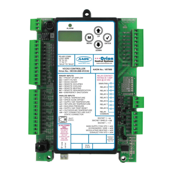
VCCX2 Controller Code: SS1088
VCC-X Controller Code: SS1079
VCB-X Controller Code: SS1051 Version 2.0 and up
VCM-X Controller Code: SS1026
VCM-X E-BUS Controller Codes: SS1030, SS1032, SS1033, SS1034
RNE Controller Code: SS1045
SA E-BUS Controller Code: Y200921
VCM Controller Code: SS1016
VAV/CAV Controller Code: SS1003 and MUA II Controller Code: SS1004
VAV/Zone Controller Codes: SS1001, SS1005, SS1025, SS8011
MiniLink PD Code: SS0040, SS1061
Advertisement
Table of Contents

Summary of Contents for Orion Control Systems SS1068
- Page 1 Modular System Manager SD Quick Start Guide Requires Modular System Manager SD Code: SS1068 VCCX2 Controller Code: SS1088 VCC-X Controller Code: SS1079 VCB-X Controller Code: SS1051 Version 2.0 and up VCM-X Controller Code: SS1026 VCM-X E-BUS Controller Codes: SS1030, SS1032, SS1033, SS1034...
- Page 2 IMPORTANT NOTICE This Quick Start guide provides instructions for operating the Modular System Manager SD. The Operator Interfaces SD Guide for each controller is available for download from our website—orioncontrols.com, or if you have the SD Card available, the technical guides can also be printed from the SD card. VCCX2 Controller - OR-VCCX2OISD-TGD VCC-X Controller - OR-VCCXOISD-TGD VCM-X &...
-
Page 3: Table Of Contents
TABLE OF CONTENTS SYSTEM CONNECTION ....................4 Description ............................... 4 Connection & Wiring ..........................5 INTERFACE OVERVIEW ....................6 Display Screens and Data Entry Keys ..................... 6 Mode Selection Buttons ........................... 6 INITIALIZATION ....................... 7 Initialization & Setting the Time & Date ....................7 Setting the Operating Mode ........................ -
Page 4: System Connection
Zone SYSTEM CONNECTION Zone Modular System Manager SD Modular System Manager SD The OE392-12 Modular System Manager SD provides a direct link to enable you to view the status and adjust the setpoints of the VCCX2, VCC-X, VCM-X, VCM-X E-BUS, VCC-X, VCB-X, RNE, 9.00"... -
Page 5: Connection & Wiring
SYSTEM CONNECTION Connection and Wiring Stand Alone and Network Connection be cut off to allow for the transformer and communication terminal wiring connections. It is recommended that you do not splice the communications wire if at all possible. The transformer should be As previously described, when the System Manager is to be connect- rated at 6 VA minimum power output. -
Page 6: Interface Overview
Zone INTERFACE OVERVIEW Zone System Manager SD Keys and Buttons Operator Interfaces Mode Selection Buttons In order to confi gure and program the Orion System controllers, The Modular System Manager is provided with “Mode Selection you must have an Operator’s Interface or a personal computer with Buttons.”... -
Page 7: Initialization
INITIALIZATION Initialization & Setting the Time & Date System Manager SD Initialization Programming the Time <1> From the Setup Screen shown below, press on your keypad to System Manager SD Initialization Screen and access the Set Time & Date Screens. Setup Screens After connecting the System Manager to the controller with the 1) Set Time &... -
Page 8: Setting The Operating Mode
Zone INITIALIZATION Zone Setting the Operating Mode Setting the Operating Mode Passcode Clearance Screen will appear as shown below. The Operating Mode is displayed on the last line of the Main Screen THIS ACTION REQUIRES as shown below. The factory default setting for the System Manager A SPECIAL HIGH LEVEL is LS (Low Speed) Stand Alone Mode. -
Page 9: Changing Passcodes
INITIALIZATION Change Passcodes System Manager Passcodes THIS ACTION REQUIRES Changing the mode of operation, updating software, changing PASSCODE CLEARANCE schedules, and changing setpoints and confi gurations require pass- Enter Passcode: XXXX code clearance. The screen below will appear if this action requires passcode clearance. -
Page 10: Loop Search
Zone INITIALIZATION Zone Loop Search and System Alarm Search Network Mode & Multiple Managers System Alarm Search Loop Search The System Manager can be used to search for all active alarms on the system. You must confi gure the MiniLink PD to allow for When the System Manager is confi... -
Page 11: Alarm & Override Search
INITIALIZATION Unit Alarm Search and Override Search System Manager Override Search Alarm Screen NO ALARMS DETECTED NOTE: In order for the Override Search to work, a Loop Search must be performed fi rst. See page 10 for de- tails. To check controllers individually for alarms, use the <ALARMS>... -
Page 12: Schedules & Holidays
Zone INITIALIZATION Zone Schedules and Holidays Scheduling Week Schedules You can access the Controller Scheduling Screens by pressing From the Unit Schedule Menu, select Week Schedules. The following <SCHEDULES> . The screen below will appear because Scheduling two screens will appear in order: requires passcode clearance. -
Page 13: Schedule Override
INITIALIZATION Holiday Scheduling and Schedule Override Holiday Start/Stop Day Selection Schedule Override From the Unit Schedule Menu, select Holiday Schedules. The fol- From the Unit Schedule Menu, select Schedule Override. The fol- lowing four screens will appear in order: lowing screen will appear: Hldy Ovrd Holiday #... -
Page 14: Appendix A - Saving, Loading, And Copying Setpoints
APPENDIX A - SAVE, LOAD, COPY SETPOINTS Saving & Copying Setpoints Copy Setpoints - Network Mode Save Setpoints - Network Mode To copy a saved setpoints fi le to other controllers on the network <SETPOINTS> From any Main screen, press . - Page 15 APPENDIX A - SAVE, LOAD, COPY SETPOINTS Restoring Previously Saved Setpoints Save & Copy Setpoints - Stand-Alone This will take you to the Save Setpoints Screen shown below. Mode Save Setpoints The instructions for Stand-Alone Mode are exactly the same as Press Enter To Save Network Mode, except that there is no need to enter a Loop number in the Unit ID number fi...
-
Page 16: Appendix B - Updating The Sd Memory Card
APPENDIX B - UPDATING THE SD CARD SD Memory Card Update Updating The SD Memory Card Once you unzip the fi le, you will see a window similar to the one below. You may need to update the SD memory card from time to time, either for a new release or to add data for another Controller. -
Page 17: Appendix C - Minilink Polling Device Configuration
APPENDIX C - MINILINK POLLING DEVICE CONFIGURATION MiniLink PD Confi guration Screens MiniLink PD Confi guration Confi guration Screen #1 - System Type In order to correctly setup the MiniLink PD, you must fi rst confi gure Polling Unit Config several parameters in regard to the type of system and operating System Type... - Page 18 APPENDIX C - MINILINK POLLING DEVICE CONFIGURATION MiniLink PD Confi guration Screens Confi guration Screens #6-65 - Alarm Polling Confi guration Screen #5 - Maverick Testing Polling Unit Config Polling Unit Config Enable Alarm Polling Maverick Testing Unit XX: Disabled: Use <...
- Page 19 NOTES Operator Interfaces SD...
- Page 20 Form: OR-QSSMSD-TGD-01F Printed in the USA October 2018 All rights reserved. Copyright 2018 AAON, Inc. 8500 NW River Park Drive Parkville, MO 64152 Phone: 866-918-1100 www.orioncontrols.com Fax (816) 505-1101...
Need help?
Do you have a question about the SS1068 and is the answer not in the manual?
Questions and answers