Table of Contents
Advertisement
Quick Links
Advertisement
Table of Contents

Subscribe to Our Youtube Channel
Summary of Contents for Fimer VSN700
- Page 1 Solar Monitoring VSN700 Data Logger Product manual...
- Page 2 For more detailed information regarding proper installation and use of this product, refer to the product manual located at www.fimer.com. ATTENTION –...
-
Page 3: Table Of Contents
6. Commissioning 6.3.1 Set a static IP address 7. Adding an FIMER weather station 8. Interfacing VSN700-05 with SCADA systems 8.3.1 Set a Static IP Address for the data logger 8.3.2 Configure the serial interfaces 8.3.3 Communication with devices by SCADA or monitoring system 9. -
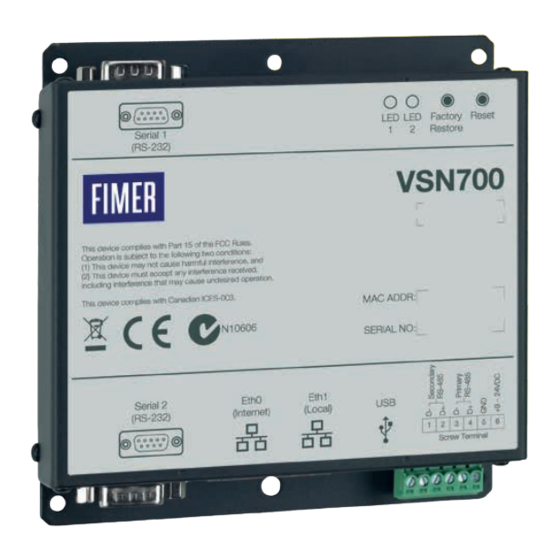
Page 4: Labels And Symbols
2. Not included in the supply FIMER accepts NO liability for failure to comply with the instructions for correct installation and will not be held responsible for systems upstream or downstream the equipment it has supplied. It is absolutely forbidden to modify the equipment. Any modification, manipulation, or alteration not expressly agreed with the manufacturer, concerning either hardware or software, shall result in the immediate cancellation of the warranty. -
Page 5: System Overview
The installer logs on to the Aurora Vision website to register the VSN700 series data logger and ensures that the logger is correctly passing information to the servers. The installer provides a URL to the end user for access to Aurora Vision Plant Viewer. The installer can also monitor all of their sites through a web-browser using Aurora Vision Plant Portfolio Manager. - Page 6 Scada The information in this document applies to all VSN700 Data Logger models. This guide provides instructions for installing the data logger hardware to work directly with FIMER (or legacy Power-One) solar inverters and for setting up the Aurora Vision management system for remote data access.
-
Page 7: Installation
3. Mount the data logger. The logger comes with flanges with pre-drilled holes for easy mounting. A DIN rail mounting kit comes with the VSN700-05-00 model and can be optionally ordered with other models. All data logger versions require a weather protected site. The included power supply requires an ambient temperature between 0oC and 40oC but the logger can operate between -40oC and 85oC. - Page 8 Attach the other solid black DC ground conductor to Port 5 of the data logger’s screw terminal. See the figure below. VSN700-05-00 models come with a DIN Rail kit for mounting directly onto a DIN rail within an inverter. After DIN Rail mounting, connect the data logger directly to a 9V-24V (±10%) DC voltage source capable of supplying greater than 7.2VA.
- Page 9 FIMER (and legacy Power-One) PVI and UNO inverter models use a proprietary communication protocol called Aurora Protocol. To monitor these inverters with a VSN700-01 (Residential) or VSN700-03 (Commercial) Data Logger model, they must be attached to the Secondary RS-485 port on the data logger.
-
Page 10: Commissioning
If no activity is seen on the LEDs, double-check all connections. FIMER recommends a wired Internet connection because it is more reliable and requires less setup. If it is necessary to connect to a wireless network, a wireless network bridge with an Ethernet port is required. Purchase and configure the wireless network bridge that is compatible with the host wireless network. -
Page 11: Set A Static Ip Address
RS-485 port. See Section 4 if you are adding a VSN800 Weather Station. See Section 5 for advanced configuration options if you are using VSN700-05 (Max). For the Secondary RS-485 connection, once inverters using the Aurora Protocol are properly addressed and wired in the RS-485 daisy chain, inverters will automatically be discovered and displayed. - Page 12 6.4 Verify Internet connectivity to Aurora Vision servers 1. Verify that the Ethernet cable is connected between the data logger’s Eth0 (Internet) and your network. 2. The data logger acts as a router. From your laptop connected to Eth1 (Local), verify internet connectivity by opening up an Internet browser window and connecting to www.auroravision.net.
- Page 13 4. A page is displayed to configure the user’s Plant Viewer options. Scroll down to the Published View section. The URL to provide to the customer is in the Share URL field. NOTE – For detailed information about plant sharing options see the Plant Portfolio Manager User Guide. Go to https://docs. auroravision.net for all the latest product documentation.
-
Page 14: Adding An Fimer Weather Station
FIMER’s VSN800 Weather Station must be wired to the Primary RS-485 port on VSN700-03 (Commercial version). Weather stations are not supported by VSN700-01 (Residential version). Weather stations can be attached to any port configured for Modbus RTU on VSN700-05 (Max version). - Page 15 4. Connect the other end of the shielded twisted-pair wire to the +9-24VDC and GND terminals (terminals 6 and 5) on the data logger. It may be necessary to use a wire nut to attach the multiple wires to the GND terminal on the data logger. Wire the weather station to the data logger as shown in the figure below.
- Page 16 The port configuration for the Primary RS-485 port on the Commercial version VSN700 (VSN700-03) must remain set to Modbus RTU (default value) if adding an optional weather station.
-
Page 17: Interfacing Vsn700-05 With Scada Systems
8. Interfacing VSN700-05 with SCADA systems This section describes how to interface external monitoring or SCADA systems with the VSN700-05 data logger and is intended only for the Max version data loggers. This section does not apply to the Residential and Commercial versions. There are two important aspects of the data logger that allow for easy integration into a SCADA system, the Aurora Protocol to SunSpec Adapter and Modbus TCP communication. - Page 18 icon next to each interface to access the Configure Interface menu(s). If communicating with inverters via Modbus TCP, open the port(s) in the firewall associated with the RS-485 interface(s) by clicking the wrench icon next to the red X to open the Configure Global Settings menu.
-
Page 19: Communication With Devices By Scada Or Monitoring System
Modbus TCP command would be pointed to: <Eth0_IP_address>:503:26. 8.4 Adding 3rd party devices If you are adding supported 3rd party devices to VSN700-05 (Max version), follow the steps below to manually add the device. Alternatively, certain Modbus RTU devices can be auto-discovered using the Find button. - Page 20 8. Press the Apply icon at the top to commit the changes. 9. After making changes, you are returned to the Devices page with the status indicators, as shown below. After sucessfully collecting the first sample the indicator will turn green; click the black triangle next to the status indicator to verify the data collected is correct. 8.5 Modbus TCP client In addition to Modbus TCP server functionality, the data logger is also capable of polling Modbus TCP devices using its Modbus TCP client interface.
-
Page 21: Troubleshooting
If the data logger was previously registered on Aurora Vision and a factory restore is performed, you have to contact FIMER Technical Support to reset the data logger login credentials. Failure to reset the credentials will prevent the data logger to login to Aurora Vision. - Page 22 Authorization). Do not return items without a RMA number displayed on the outside of the package. If you require an advance replacement to be shipped before the RMA unit has been received by FIMER, you will need to submit a valid purchase order for the replacement unit, referencing the RMA number on the P.O.
-
Page 23: Data Logger Specifications
• VSN700-01 (Residential): Up to 5 FIMER (or legacy Power-One) single-phase or small three-phase (Trio 5.8/7.5/8.5) string inverters. • VSN700-3 (Commercial): Up to 10 FIMER (or legacy Power-One) string inverters and one FIMER weather station. String inverters can be single-phase or three-phase. - Page 24 Network Hosts The logger will connect to the following hosts. Some servers owned by FIMER, and others are customer or ISP servers. Servers listed as owned by “Customer IT/ISP” must be configured in the logger using either DHCP or as static network information.
- Page 27 ENGLISH ITALIANO DEUTSCH ESPAÑOL FRANÇAIS The symbol of the crossed-out wheeled bin Il simbolo del contenitore di spazzatura Mit dem Symbol der ausgekreuzten Mülltonne El símbolo del contenedor de basura tachado Le symbole de poubelle interdite identifie les identifies electrical and electronic equipment su ruote barrato, accompagnato da una werden Elektro-...
- Page 28 ČESKY ΕΛΛΗΝΙΚΆ POLSKI SLOVENČINA SLOVENŠČINA Symbol přeškrtnuté popelnice na kolečkách Το σύμβολο με τον διαγεγραμμένο τροχήλατο Symbol przekreślonego kosza na śmierci Symbol preškrtnutej odpadkovej nádoby na Simbol prečrtanega koša za smeti na kolesih označuje elektrické a elektronické zařízení κάδο προσδιορίζει ηλεκτρικό και ηλεκτρονικό na kółkach na sprzęcie elektrycznym i kolieskach označuje elektrické...
- Page 29 FIMER does utilization of its contents – in whole or in parts – is not accept any responsibility whatsoever for forbidden without prior written consent of FIMER. fimer.com potential errors or possible lack of information in Copyright©...
Need help?
Do you have a question about the VSN700 and is the answer not in the manual?
Questions and answers