Table of Contents
Advertisement
Quick Links
Advertisement
Table of Contents

Summary of Contents for XtendLan XL-PBW224CW
- Page 1 XL-PBW224CW Coaxial Integrated Access System V1.0...
- Page 2 Statement All rights reserved By the written per mission of the Company and no unit or individual will be allowed to extract the contents of this book to copy some or all of any form is not able to disseminate As the product version upgrades or other reasons for the content of this manual will be updated from time to time unless otherwise agreed by the parties to use this manual only as a guide.
-
Page 3: Table Of Contents
C ontent s Welcome to coax XL-PBW224CW Integrated Access System Recognizing XL-PBW224CW_ 1.2 XL-PBW224CW System Products 1.2.1XL-PB224C Terminal Products Appearance of the products Indicator 1.1.2 Ports 1.1.3 Connection 2.1 Connect power and network 2.1.1 Connect network 2.1.2 Connect Power 3 XL-PB224C Information Interface 3.1 Login Page... - Page 4 4.1.2 Environmental Characteristics Application Characteristics 4.1.3 Manage and Maintain 4.1.4 Adjust Technology 4.1.5 Instruction and ports 4.1.6 Frequently Questions answer...
-
Page 5: Welcome To Coax Xl-Pbw224Cw Integrated Access System
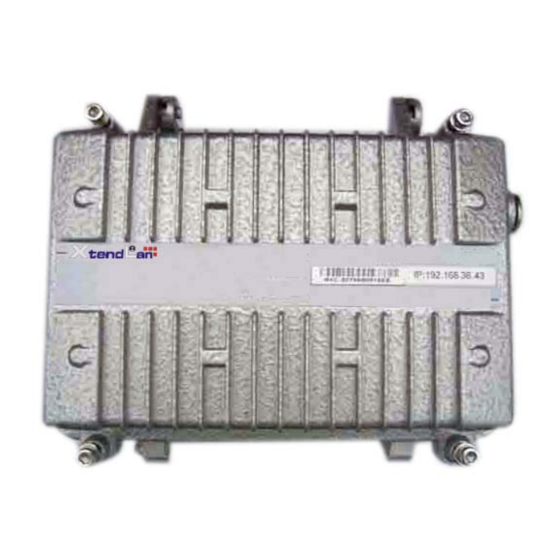
• Support for VoIP and IPTV and other IP ser vice access network for data transmission XL-PBW224CW system to bring in the enjoyment of your video / data multiple experience before you recognize your system XL-PBW224CW. 1.2 XL-PBW224CW system products XL-PBW224CW system includes headend equipment and terminal equipment. - Page 6 1.1.1 XL-PBW224CW End Products Appearance...
-
Page 7: Indicator
1.1.2 Indicator Item Meaning Desctription POWER Power Indicator Light Always have electricity, you can start using the XL-PBW224CW. System System Indicator The system to start successfully. Data Data Indicator Successfully connected to the network. Flicker:There are data transmission Ethernet LAN port connected to the network. Flicker: There are network data transmission. -
Page 8: Connection
1.In this step, please confirm your power connector and the power outlet XL-PBW224CW line voltage and current at the sa me time is also in line with XL-PBW224CW work. 2. The excha nge received a power outlet plugs, XL-PBW224CW to boot. -
Page 9: Xl-Pb224C Information Interface
3 XL-PBW224CW Information Interface XL-PBW224CW easy to set up, simple operation, users do not need to carry out any operation. XL-PBW224CW random will be attached to one for the equipment condition monitoring of private IP addresses, you can use a web browser through the IP address of the page to enter the state of the state of obser vation equipment. -
Page 10: Bridge Page
3.2 Bridge Page Pic 3-2-1 3.2.1 The basic configuration system information Pic3-2-2... -
Page 11: Bridgesystems To Send And Receive Data Packets Statistics
3.2.2 BridgeSystems to send and receive data packets statistics Pic3-2-3 3.2.3 IP Address distribution Pic3-2-4... -
Page 12: Plc Page
3.3 PLC Page Pic3-3-1 3.3.1 PLC System Equipment Information Pic3-3-2... -
Page 13: Plc System Equipment Style
3.3.2 PLC System Equipment style Pic3-3-3 3.3.3 PLC Flow Control Systems and Equipment Click on "TC ACTIVE" In the "Rate" column need to limit the rate of input Click "Save Configuration" button to save Pic3-3-4... -
Page 14: Plc Systems To Send And Receive Data Packets Statistics
3.3.4 PLC Systems to send and receive data packets statistics Pic 3-Pic-5 3.4 Ethernet Page Pic 3-Pic-1... -
Page 15: Ethernet Link Layer Information
3.4.1 Ethernet link layer information Pic 3-Pic-2 3.4.2 Ethernet Systems to send and receive data packets statistics Pic 3-Pic-3... -
Page 16: Software Page
3.5.1 Current software version information Click on "TC ACTIVE" In the "Rate" column need to limit the rate of input Click "Save Configuration" button to save Pic 3-Pic-4 3.5 Software Page... -
Page 17: Current Software Version Information
3.5.1 Current software version information 3-Pic-2 3.5.2 Delete procecures Backup software to choose a name Click Remove button. Pic 3-Pic-3... -
Page 18: Upload Upgrade Procedures
3.5.3 Upload upgrade procedures Enter promotion procedures need to upload the file name Enter FTP ser ver IP address Enter the display name in the machine Click "send" button 图 3-Pic-4 3.5.4 Change Keywords Enter the need to amend the new password Re-enter new password to confirm... -
Page 19: Vlan Page
Pic 3-Pic-5 VLAN Page Enter the need for the VID, click "add" button to add a VLAN 3-Pic... -
Page 20: Attachment
4 Attachment 4.1 Specification 4.1.1 Products Specification Item IEEE802.3、IEEE802.3u Network standard IEEE HomePlug BPL Link standard 224Mbps Physical layer bandwidth Data throughput Exclusive or shared 50Mbps 2-30MHz Work of the band work of a frequency bandwidth Single Frequency 28MHz, Broadband multi-carrier 7 (Wavelet) X128 (carrier) = 896 (Carrier) number frequency division duplex / full-time... - Page 21 IP Multicast IGMP snooping through the realization of 802.3 multicast and m...
-
Page 22: Manage And Maintain
ulticast, multicast group of end-use of a common tone map in order to optimize data throughput. 4.1.4 Manage and Maintain Manage Telnet、SNMP 4.1.5 Modulation OFDM Modulation TDMA+CSMA/CA Modulation None、BPSK、QPSK、16QAM、64QAM、256QAM、1024QAM Modulation Way 4.1.6 Instruction and Ports Power power equipment status indicator LED Power indicator Ethernet Ethernet indicator light System System Indicator... -
Page 23: Frequently Questions Answer
4.2 Frequency Question Answer Solution Trouble phenomenon POWER light does not 1, check the power connector is correct. shine 2, check the power adapter match Ethernet Light does not 1,Check the validit y of the cable connections, check whether the PC shine card's indicator light lit.
Need help?
Do you have a question about the XL-PBW224CW and is the answer not in the manual?
Questions and answers