Table of Contents
Advertisement
Quick Links
Introduction
The EMS-3 is a multifunction engine information display and early warning engine monitoring system. It has been
specifically designed to monitor crucial vehicle information, and in the event of any engine irregularities, it will alert the
driver by means of a visual and audible alarm.
With its array of advanced features, the EMS-3 is an indispensable unit for the discerning vehicle owner. Costly
maintenance bills can easily be avoided by the prevention of major engine problems before they occur.
Madman EMS-3
Universal Engine Monitoring System
Operating Manual – English 1.04
Advertisement
Table of Contents

Related Manuals for MadMan EMS-3

Summary of Contents for MadMan EMS-3
- Page 1 With its array of advanced features, the EMS-3 is an indispensable unit for the discerning vehicle owner. Costly maintenance bills can easily be avoided by the prevention of major engine problems before they occur.
- Page 2 Large 1.8” high resolution 160x128, sunlight readable, wide viewing angle, 1000 cd/m2 TFT LCD display Battery voltage display, the EMS-3 can measure voltages up to 30V (Can be used in 12V and 24V vehicles) and contains a programmable low/high voltage alarm to automatically catch alternator failures, drive belt failures and bad batteries ...
-
Page 3: Main Displays
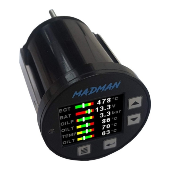
Madman EMS-3 Operating Manual Page 3 2 Layout 2” (52mm) enclosure. Sunlight readable color graphic display Up Button: Menu System: Up button / Increment Normal: Scroll through main display Ambient light sensor for screens automatic backlight control. Down Button: Harness connects to power... -
Page 4: Pressure Display
3.4 Oil Pressure Switch Message The EMS-3 can also be used to display a warning message from a switch type oil pressure sender. These senders can be of a NO (Normally Open) or a NC (Normally Closed) type sender. The oil pressure switch uses the analog 4 input channel. -
Page 5: Temperature Display
The EMS-3 uses standard automotive temperature senders to display the temperature. The EMS-3 also contains fail safe temperature inputs to alert the user when the sender has been disconnected or faulty. The EMS-3 supports 120 and 150 VDO senders, a precision temperature sender, Echlin TS920SA or a custom user definable temperature sender curve. -
Page 6: Exiting The Menu System
Madman EMS-3 Operating Manual Page 6 4 Menu System Press the menu button during the normal display mode to enter the menu system. Use the Up / Down keys to navigate through the menu system. 4.1 Exiting the menu system Press the Menu button to exit the menu system when the “EXIT”... - Page 7 Madman EMS-3 Operating Manual Page 7 4.2 EGT (Exhaust Gas Temperature Setup) Display: Select "ON" to enable the EGT display. Label: Enter a label to suit your EGT Channel so you can easily identify it. Display Max: Select the maximum temperature that you want the EGT bargraph to show. This can give you increased display resolution.
- Page 8 Madman EMS-3 Operating Manual Page 8 Probe: Select if you are using a K-type or J-type thermocouple probe. Unit: Select whether you want the temperature to be displayed in degrees Celsius (ºC) or degrees Fahrenheit (ºF).
-
Page 9: Pressure Setup
Madman EMS-3 Operating Manual Page 9 4.3 Analog CH1 to CH4 Setup The 4 analog channels are universal analog input channels that can be used for pressure, temperature etc. Only “CHANNEL 1” Setup is shown below, follow the same steps for Channel 2, 3 & 4 4.3.1 Pressure Setup... - Page 10 Madman EMS-3 Operating Manual Page 10 Sender: Select what type of resistive pressure sender you are using. Select “VDO” for VDO / resistive senders, “USER” for a custom sender. Model: Select which VDO pressure sender you are using. A selection between a VDO 2, 5 or 10 Bar can be selected.
-
Page 11: High Alarm
Madman EMS-3 Operating Manual Page 11 High Alarm: Enter the pressure threshold for when the high alarm must be activated. Any pressure above this value will activate the alarm. High Caution: Enter the pressure value for the high caution. This is the lower value of the upper yellow band. - Page 12 If the sender type is set to LM335, then use this menu option to calibrate your LM335 precision temperature sender. If recalibration is required then adjust the value until the temperature matches the reference ambient temperature. Please note that the LM335 can only be calibrated in degrees Celsius irrespective if the EMS-3 is setup to display temperature in Fahrenheit.
- Page 13 Madman EMS-3 Operating Manual Page 13 4.3.3 Calibrating the user defined pressure and temperature senders 1. Enter the number of points that you want to calibrate. 2. Enter the display reading that you want to show when the sender is at that actual display reading.
- Page 14 Madman EMS-3 Operating Manual Page 14 4.4 Volts Setup Display: Select "ON" to enable the Volts display Label: Enter a label to easily identify your Volts reading. Display Max: Select the maximum value that you want the volts bargraph to show. This can give you increased display resolution.
-
Page 15: Switch Time
Madman EMS-3 Operating Manual Page 15 Low Alarm: Enter the voltage threshold for when the low alarm must be activated. Any voltage below this value will activate the alarm. Alarm: Select which output the alarm must activate. Cal: Measure the battery voltage with a multimeter and then adjust this value to match that of the multimeters volts reading. - Page 16 Madman EMS-3 Operating Manual Page 16 4.6 RPM Setup Display: Select if you want the RPM to be displayed in “RPM”, “PERCENT” or “OFF”. RPM 100%: Select the maximum value that you want the RPM to correlate to 100%. This is only shown if “Percent” is selected for display.
-
Page 17: Low Alarm
Madman EMS-3 Operating Manual Page 17 Low Alarm: This enables or disables the RPM low alarm. Low Alarm: Enter the RPM threshold for when the low alarm must be activated. Any RPM value below this value will activate the alarm. - Page 18 Madman EMS-3 Operating Manual Page 18 4.8 Output Setup (Fan control) Mode: Select "FAN CNTRL" to enable the fan control output. Analog CH: Select which analog temperature channel the fan control must operate from. Fan On Temp: Enter the temperature when the output must switch on.
-
Page 19: Timers Setup
Madman EMS-3 Operating Manual Page 19 4.9 Timers Setup Set Hour Meter: This function allows you to set the engine hour meter to any value. Typically, you would use this function to set the hour meter to the current known engine time. If the hour meter code is set to another value beside zero, then the user will be prompted to enter the hour meter access code before allowing him to change the hour meter time. - Page 20 Select which output the alarm must activate when the service timer reaches zero. Start: Select if the EMS-3 must start the hour meter and service timer from power up or from when a pre-selected volts threshold has been exceeded. Volts:...
-
Page 21: Protocol Format
Serial Out: Select “ON” to enable the RS232 serial output. Unit Address: Enter the EMS-3 unit address. Baud Rate: Select the desired baud rate of the serial output. The transmission format is set to 8 data bits, No parity, 1 stop bit. - Page 22 Madman EMS-3 Operating Manual Page 22 Message type=128 Data Length=29 bytes Output Rate=1Hz Unused channels will read 0 Hour Meter Hours: Unsigned Int (16 bits), Hour meter hours Hour Meter Minutes: Unsigned char (8 bits), Hour meter minutes Service Time:...
-
Page 23: Security Setup
Madman EMS-3 Operating Manual Page 23 4.11 MISC Setup (Miscellaneous Setup) Backlight: Select manual or automatic backlight control. Use the Up / Down keys in manual mode to adjust the backlight brightness. Allow 3 seconds for the display to adjust to the ambient lighting conditions when using the automatic backlight mode. -
Page 24: Adc Values
Madman EMS-3 Operating Manual Page 24 Information: This menu option displays information about the unit. Default Settings: Select this menu option to reset all the settings to factory defaults. Sound: Select "ON" to turn the external buzzer sound on. 4.12 ADC Values This menu displays the ADC values of the various sensors. -
Page 25: Error Messages
Madman EMS-3 Operating Manual Page 25 6 Error Messages Unit settings CRC error. Load default settings to restore to factory defaults. If the error message still persists then it could possibly be a non-volatile memory failure in which case the instrument will then have to be returned to the factory. -
Page 26: Specifications
Resistive Senders: The EMS-3 supports resistive type pressure senders. VDO Resistive Senders: The EMS-3 supports the VDO 2, 5 and 10 Bar senders. VDO pressure senders used to measure fuel pressure require the fuel isolation kit available from VDO. 4-20mA Senders: The EMS-3 supports 4-20mA current output pressure senders. -
Page 27: Firmware Upgrading
0.25A DC which can be used to drive an auto relay, piezo buzzer or LED. 9 Firmware Upgrading The EMS-3 can be upgraded in the field by connecting the RS232 port to a PC and running the firmware update program. Please see the Madman EMS-3 firmware upgrading document for more information. -
Page 28: Installation
10.1 Connection Diagram The use of an external 1A fuse is recommended. Connect the supply terminals to your vehicles power supply. The EMS-3 can be used on both 12V and 24V without the use of any pre-regulators. Ensure that the supply voltage will not drop below 8V during operation as this may result in incorrect readings. - Page 29 Madman EMS-3 Operating Manual Page 29 10.2 Cable connections (Molex Microfit 3.0) Looking at the rear of the EMS-3 instrument Color Function White EGT Probe – (K Type Red lead) Orange EGT Probe + (K Type Yellow lead) Brown Coolant Level Detector (CLD input)
- Page 30 – if this is the case then the plates can be removed and tapped to accommodate the EGT probe. Your Madman supplier should then also have this plate in stock as a listed adapter for that engine. If you have an EGR valve fitted, remove it entirely and disable the diaphragm by removing the wiring loom or vacuum pipe.
-
Page 31: Coolant Temperature
The sandwich has a port in it to take the temperature sender. Check your vehicles installation details on the MadMan web site to see if a plug adapter is available. If we do not list one, we have either not developed one for your engine yet or it cannot use a sandwich adapter. -
Page 32: Oil Pressure
Cut the hose here and insert the hose adapter and refit the hose to the other side of the pipe with clamps. Fit the brown wire from the EMS-3 to the pipe. The return path is via the EMS earth wire already installed –... - Page 33 The internal pull up resistor dip switch for the resistive temperature sender input must be in the “ON” position. User defined senders: The EMS-3 has a user sender calibration feature that can be customized for senders not listed above. 10.11 Pressure senders Resistive senders: The EMS-3 supports resistive type pressure senders.
- Page 34 10.13 Analog Channels Dipswitch settings The EMS-3 unit has the added ability, over its predecessors, to use both resistance and voltage based sensors. In order to make use of this wider range of sensors, a small bank of on-off switches has been mounted on the input PC board inside the EMS-3 housing to enable sensor compatibility selection.
-
Page 35: Dimensional Drawing
Madman EMS-3 Operating Manual Page 35 10.14 Dimensional Drawing The drilled mounting hole must have a diameter of 53mm. The maximum panel thickness is 15mm, but the mounting bracket can be modified to accommodate thicker panels. -
Page 36: Warranty
IMPORTANT NOTICE: You must make your own determination if the products sold by Madman Developments (Pty) Ltd are safe and effective for your intended applications. Madman Developments (Pty) Ltd makes no representations or warranties as to either the... - Page 37 Madman EMS-3 Operating Manual Page 37 DISTRIBUTED BY: Madman Developments (Pty) Ltd Postal Address: PO Box 1391 Muldersdrift Gauteng 1747 South Africa Website: www.madman.co.za Email: sales@madman.co.za...
Need help?
Do you have a question about the EMS-3 and is the answer not in the manual?
Questions and answers