
Related Manuals for HIGHLEAD GC0618-1 SC


Summary of Contents for HIGHLEAD GC0618-1 SC
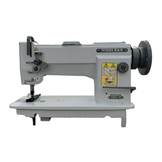
- Page 1 GC0618-1/-SC/-D2/GC0518-1 Heavy Duty Compound Feed Lockstitch Sewing Machine Instruction Manual Parts Catalog...
- Page 2 1 ) Avoid using the machine at abnormally high temperature (35°C or higher) or low temperature (5°C or lower) 2 ) Avoid using the machine in dusty conditions. 2 MAIN SPECIFICATIONS Item GC0618-1 GC0618-1 SC GC0618-1 D2 GC0518-1 Max. Sewing Speed 2000rpm Stitch Length...
- Page 3 PREPARATION AND LUBRICATION 1 ) Cleaning the machine Before leaving the factory, the machine parts are coated with rust-preventive grease, which may be hardened and contaminated by dust during storage and shipment This grease must be removed with gasoline. 2 ) Examination Though every machine is confirmed by strict inspection and test before leaving the factory, the machine parts may be loose or deformed after long distance transportation with jolt.
- Page 4 4 REPLACE NEEDLES (Fig 5) 1 ) Turn the balance wheel to lift needle bar 1 to the upper end of its stroke. 2 ) Loosen needle clamp screw 2. While keeping the long groove of the needle leftward fully insert the needle shank up to the bottom of the needle socket.
- Page 5 REMOVING AND Fig 7 INSERTING THE BOBBIN 1 ) Turn the balance wheel to lift needle bar 1 to the upper end of its stroke. Place the feed dog at this side in its travel turning the balance wheel, and open the slide plate A. (Fig 7) 2 ) Open on the drip pan, and then open the hinged latch with left thumb and index finger.
- Page 6 1 Well balanced 2 Upper thread strong 3 Upper thread weak or lower thread weak or lower thread strong Fig 9 9 REGULATING THE THREAD TENSIONS For ordinary stitching, the tension of the upper and the lower threads should be equal so as to lock both threads in the center of the material.
- Page 7 11 ADJUSTING THE LIFT OF THE ALTERNATING PRESSER FEET (Fig 10) Fig 10 The thickness of the material should control the height of the lift of the alternating presser Fig 10 feet. The lift should be just enough for clearance of the material. Fig 10 1 ) With normal adjustment both feed lift to equal height: To later lift, loosen the wing nut A and move the link and stud assembly along the slot-move up to raise the feeding presser foot and...
- Page 8 14 RELATIVE POSITION Fig 13 OF THE FEED DOG TO NEEDLE PLATE (Fig 13) Fig 13 1 ) Set the stitch length at minimum. Fig 13 2 ) Turn the balance wheel so as to raise the feed dog to its highest point. 32.1mm 3 ) Lay down the machine head toward the other side and loosen the screw 5 (Fig 4).
- Page 9 1 ) Loosen the screw 1 for cover plate 2 and then remove the cover plate 2. 2 ) Normally put the arrow mark 7 of the cam 6 on the “V” ditch 5 of arm shaft. Then tighten the cam screw.
- Page 10 Fig 19 18 TIMING BETWEEN THE HOOK AND THE NEEDLE (Figs 18, 19) After setting the needle bar height, set stitch length to minimum, turn the balance wheel toward you until the needle bar reaches its lowest point. Continue turning and allow the needle bar to raise about 2mm while Fig 20 on its upward stroke.
- Page 11 20 TIMING OF THE VIBRATING PRESSER FOOT This is the normal liming when turn the balance wheel toward you, after lowering the presser bar lifter, the vibrating presser foot should reach the feed dog earlier than the needle eye comes to, and when the needle raises, the vibrating presser foot should leave the feed dog after the needle eye has left the feeder.
- Page 12 Fig 22 Adjusting tool Pully Before After 23 ADJUSTMENT 3rd mark OF NEEDLE BAR Rotating Fig 23 STOP POSITION direction (Figs 22, 23) 1st mark 1 ) Adjusting of “UP” position When the pedal is kicked down by heel, the machine stops at “UP” position.
- Page 13 24 ADJUSTMENT OF Fixed blade KNIFE ENGAGEMENT Moveable 7.5mm knife (left) (Fig 24) 1 ) Position of movable knife (left) and fixed blade: See the illustration. The standard distances from the needle center are Knife driving crank 7.5mm and 7mm from the movable knife (left) and fixed blade respectively.