Table of Contents
Advertisement
Quick Links
Advertisement
Table of Contents

Subscribe to Our Youtube Channel
Summary of Contents for Plettenberg MST60-80
- Page 1 Operational Manual Plettenberg Motor control MST-60-80 V5.1 MST60-80 Plettenberg Elektromotoren GmbH & Co. KG Rostocker Str. 30 D-34225 Baunatal Telefon: +49 (0) 56 01 / 97 96-0 Fax: +49 (0) 56 01 / 97 96-11 Internet: http://www.plettenberg-motoren.com e-Mail: info@plettenberg-motoren.com S. 1...
-
Page 2: Table Of Contents
Operational Manual Plettenberg Motor control MST-60-80 V5.1 Table of Contents Chapter Seite 1 Introduction ........3 2 Technical Data . -
Page 3: Introduction
RS232 interface in plain text so that they can be evaluated with a PC or other microprocessor control easy. The firmware of the MST60-80 can be updated. However, it has to be sent to the factory for update. -
Page 4: Technical Data
Operational Manual Plettenberg Motor control MST-60-80 V5.1 Technical Data : Weight: approx. 230g without connectors Length: 112mm with flange, 95mm without flange Width: 56mm Height: 19 mm without connector Protection class: IP40 Maximum Speed: 240000rpm electrical Maximum continuous power 4800W... -
Page 5: Drawing Including Connections
Operational Manual Plettenberg Motor control MST-60-80 V5.1 S. 5... -
Page 6: Mounting And Connection Rules
For example, if you use 33cm battery cables length for the MST60-80 you have 100cm – 2 x 33cm = 34cm total cable length left for the battery pack. The allowed cable length depends also on the current, so if you are using the controller at higher currents than the nominal current, the allowed cable length is shorter. -
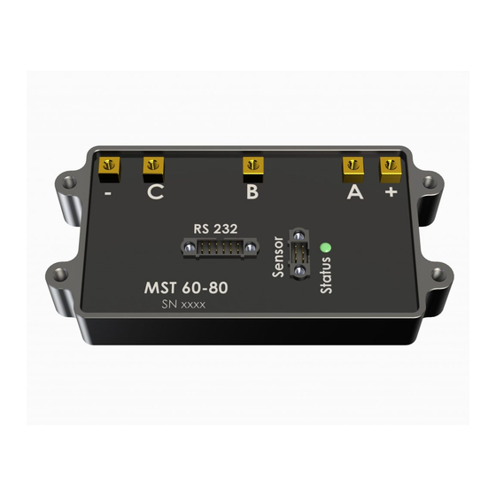
Page 7: Connectors And Pin Assignment
Operational Manual Plettenberg Motor control MST-60-80 V5.1 connectors and pin assignment: Please read the assembly instructions of the Harwin Datamate J-Tek series carefully: https://cdn.harwin.com/pdfs/C005XX_M80_and_M83_Datamate_Series_Connectors.pdf We recommend the crimp tool M22520/2-01 selector setting 6 with the positioner T5747/K1419. Row1 uneven pin numbers, row2 even pin numbers... -
Page 8: Safety Functions
Operational Manual Plettenberg Motor control MST-60-80 V5.1 Warning: Even a short-term short-circuit on the 5V supply at the control connector leads to the failure of the power supply of the Hall sensors. This can cause a defect at the motor controller if the engine is running. -
Page 9: Safety Notes
Operational Manual Plettenberg Motor control MST-60-80 V5.1 Safety notes : Over 60V battery voltage you leave the range of the Safety Extra Low Voltage! The wiring must be carried out at supply voltages above 60V only by qualified persons. It must be considered the relevant technical standards. Touching the motor terminals with the engine running with more than 60V battery voltage can cause injuries. - Page 10 For example, if a 20A rated motor operated at the MST60-80, the current monitoring in the case of blocking will not detect an excessive current and the motor may be destroyed.
-
Page 11: Initial Operation Of The Drive System
Operational Manual Plettenberg Motor control MST-60-80 V5.1 Initial operation of the drive system: For the first test of the wiring of the drive system, we recommend to use a current limited power supply. A power supply with an output voltage of 12V will do the job. At the first time please use only low throttle, if the motor is running rough or only vibrates, put the throttle back to zero and disconnect the battery cables. -
Page 12: Led Indicator Functions
Operational Manual Plettenberg Motor control MST-60-80 V5.1 ImpulsStop/Start/Full = 1150µs/1200µs/1900µs For. Throttle Inc/Dec = / 328 For. Throttle Max/Min = 100% / Rev. Throttle Inc/Dec = / 328 Rev. Throttle Max/Min = 100% / Brake Inc/Dec / 328 Brake Max/Min... -
Page 13: Standard Setup Values
Operational Manual Plettenberg Motor control MST-60-80 V5.1 Standard Setup Values: Input = Analog AnalogStop/Start/Full/BrakeMax = 500mV/ 549mV/4499mV/4499mV Impuls Stop/Start/Full = 1150µs/1200µs/1900µs For. Throttle Inc/Dec = 328 / 328 For. Throttle Max/Min = 100% / 3% Rev. Throttle Inc/Dec = 66 / 328 Rev. -
Page 14: Rs232-Interface-Commands
Operational Manual Plettenberg Motor control MST-60-80 V5.1 RS232-Interface-Commands : 1 Byte Commands: "s": switch to serial RS232 Input "p": switch to analog input(Poti) "i" : switch to impulse input(compatible with model radio control) "f": forward "r": reverse "0": Motor off "b":... - Page 15 RS232 Command examples: 1. CR/LF is not necessary 2. After connecting the supply voltage to the MST60-80 controller the analog input is active by default. If you want to use the serial control input, you have to send „s“ after the initialization of the controller.
-
Page 16: Sensor Phase Mapping
Operational Manual Plettenberg Motor control MST-60-80 V5.1 Sensor Phase Mapping Commutation Sequence Forward Step1 Step2 Step3 Step4 Step5 Step6 Error1 Error2 Phase A(U) Phase B(V) Phase C(W) Sensor A Sensor B Sensor C Commutation Sequence Reverse Step1 Step2 Step3 Step4 Step5 Step6 Error1 Error2... -
Page 17: Legal Terms And Conditions
Operational Manual Plettenberg Motor control MST-60-80 V5.1 Rechtliches: Es wird keine Haftung übernommen für Sach- und Vermögensschäden, sowie Sach- und Vermögensfolgeschäden: durch unsachgemäße Handhabung. an sämtlichen Fluggeräten wie Ultraleichtflugzeugen, Drachen, Fallschirmen, Flugmodellen, Raketen, Drohnen, Hängegleitern und Gleitseglern oder deren Teilen, sowie Schäden durch Grounding von o.g.
Need help?
Do you have a question about the MST60-80 and is the answer not in the manual?
Questions and answers