
Summary of Contents for Rainman WM Series
- Page 1 WM and WMR Series High Pressure Pump Service Rainman Technology Pty Ltd #17 / 10-18 Orchard Road Brookvale, NSW 2100 Australia www.rainmandesal.com support@rainmandesal.com +61 433 826 626 Version 1.1...
-
Page 2: Table Of Contents
Table of Contents Pump Description Routine Pump Maintenance Oil Change Preventing Cavitation Replacing the Valves Overview Procedure Replacing the Packings Overview Procedure Setting Relief Valve Troubleshooting Maintenance Log... -
Page 3: Pump Description
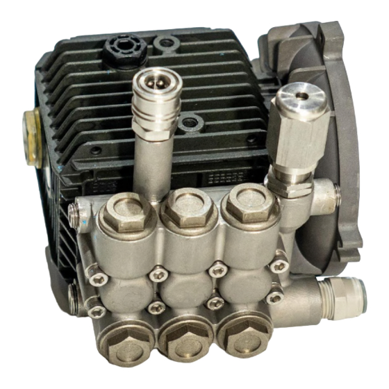
If you have the older Mk1 electric (either AC or 12VDC) manufactured through January 2019, or any petrol (gasoline) model, your system will have a General Pump WM Series pump. If you own an electric (AC or 12VDC) Mk2 system, manufactured after February 2019, your system will have a General Pump WMR Series pump. -
Page 4: Routine Pump Maintenance
Exploded view of WMR series pump showing pistons and manifold Routine Pump Maintenance Very little routine maintenance is required on your General Pump high pressure pump. Required maintenance is in your operations manual, but is also included here for completeness of this document. Oil Change When replacing the oil in the pump, use SAE-30 weight oil. -
Page 5: Replacing The Valves
Replacing the Valves Overview Each of the three cylinders in the pump has two spring loaded one way valves. One valve allows water to be pushed into the cylinder by the lift pump as the piston retracts. The second valve opens as the piston forces the water under high pressure through the manifold. -
Page 6: Procedure
Procedure Using a 22mm spanner or socket, remove the valve cap. Examine threads and O-ring. Replace O-ring (item 1) if there is any evidence of cuts, abrasions, distortion or wear. Remove valve assembly (item 2) from valve cavity. Remove valve seat O-ring (item 3) from valve cavity. Inspect manifold for wear or damage. - Page 7 Insert valve assembly (item 2) into valve cap as shown. Coat the threads of the valve cap with anti-seize grease (such as Renolit ST-80) and reinstall valve cap. Torque to 40 Nm (30 Ft-Lbs). High Pressure Pump Servicing Instructions – Page 5...
-
Page 8: Replacing The Packings
Replacing the Packings Overview The purpose of the packings is to allow the pump to push water through at high pressure while also preventing it from leaking out of the pump along the pistons. The hard high pressure seals contain the pressure within the manifold of the pump, but some moisture slides out with the piston on each stroke. -
Page 9: Procedure
In the photo to the right are the following seals from top to bottom: • Low pressure seal (item 2 in diagram).This is the one with stainless steel spring visible inside . • Stainless ring case (item 4 in diagram) with O-ring (item 3). - Page 10 Remove the stainless steel case (item 3 / 4) where low pressure seals (item 2) were installed. Tightness of stainless casings varies from pump to pump. It may be possible to remove the rings by inserting a finger and pulling outwards. If more force is necessary, use a 17-18mm diameter object (such as a blind bearing puller or screwdriver handle) and gently pull them out with a slight rocking motion.
- Page 11 Set the high pressure seal insertion guide (item 8) in manifold cylinder. Do not grease any portion of the packing assembly during this step. Gently place assembled glyd rings (items 5 / 6) inside insertion guide (item 8) so they are resting evenly. Insert pusher tool (item 9), blunt end facing forward and firmly press down to set glyd rings (items 5 / 6) in the manifold.
- Page 12 10. Set low pressure seal guide (item 7) over seal casing (item 3 / 4) ensuring recess for seal is facing upwards. 11. Gently place low pressure seal (item 2) into the guide (item 7) ensuring the open spring side of the seal is facing toward the casing and resting evenly.
- Page 13 13. Confirm that the O-ring is in the correct groove on casing (item 3 / 4). At this point you should not be able to see the spring in the low pressure seal (item 2) as it should be facing toward the casing itself. 14.
-
Page 14: Setting Relief Valve
(1000 psi) it will be completely open, limiting the maximum output pressure of the PSU to approximately 69 bar (1000 psi). All relief valves are set in the Rainman factory during final testing of each system. In the highly unlikely event that a relief valve needs to be replaced, it will need to be set to the correct opening pressure. - Page 15 Note that the VS100 relief valve is installed upside down on the Mk1 Electric PSU with the WM pump. Directions here are given as if you are looking at the end hexagonal adjustment cap. Once you have replaced the relief valve, and before replacing the plastic case of your PSU, reconnect the particle filter housing so that you can perform the following steps.
-
Page 16: Troubleshooting
Troubleshooting The troubleshooting table is highly technical and specific only to the high pressure pump, not your Rainman watermaker in general. In the vast majority of operational troubleshooting issues, you should utilise the table in the general operations manual. High Pressure Pump Servicing Instructions – Page 14... -
Page 17: Maintenance Log
Maintenance Log High Pressure Pump Servicing Instructions – Page 15...
Need help?
Do you have a question about the WM Series and is the answer not in the manual?
Questions and answers