Table of Contents

Advertisement

Quick Links

800 Series
Models 850, 860
OEM
Integration
Manual
PN: 85-03431
Rev C
Dec-01

Advertisement

Table of Contents
loading
Need help?

Need help?

Do you have a question about the 800 Series and is the answer not in the manual?

Questions and answers

Summary of Contents for Ithaca 800 Series

  • Page 1 800 Series Models 850, 860 Integration Manual PN: 85-03431 Rev C Dec-01...
  • Page 3 Change History Rev A Initial Release Rev B Updated all views to match current geometry. Included commands (GS a ). Rev C Added Buzzer, ticket switch, and LED information. Dec-01 Rev C Page Confidential Information: Not for Distribution.
  • Page 4: Important

    Losses that can be attributed to improper installation and working procedures are not the responsibility of TransAct Technologies Inc. No part of this manual may be used to recreate any part of the 800 Series Printer. This manual is to be used for integration purposes only. If this manual contains any questionable information or mistakes please contact TransAct for assistance.
  • Page 5: Table Of Contents

    Internet Support............................. 1 www.transact-tech.com........................1 Service Information..........................2 Ithaca Product Support Procedure ......................2 Contacting TransAct’ s Ithaca Facility ....................3 SERIES 800 SPECIFICATIONS AND REQUIREMENTS Series 800 Model Functionality Descriptions ..................4 Standard Features ..........................4 Optional Features........................... 5 Dimensions ............................
  • Page 6 Racking/Unracking the Printer Mechanism Assembly ............... 22 Loading Tickets into Feeding Mechanism..................23 Removing Loaded Tickets........................24 Cleaning the Print Head ........................26 PROGRAMMING FOR THE 800 SERIES Resetting the Printer .......................... 27 Command Parameters........................27 Character Evaluation ......................... 27 16-bit Character Parameters ......................
  • Page 7: Table Of Contents

    Table of Contents 800 Series OEM Integration Manual ESC @ Reset to Power-up Condition..................39 ESC E Form Feed ........................40 Feed n Sublines ......................40 ESC J ESC M Set Font to 12 cpi......................41 ESC P Set Font to 16 cpi......................41 ESC T Set Font to 7 cpi......................
  • Page 8 Figures 
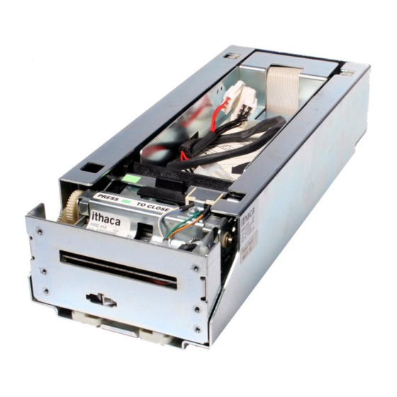
Figure 1 800 Series Printer Component Overview........................4 Figure 2 Series 800 Printer: Dimensions............................6 Figure 3 Design Envelope: Ticket Clearance..........................10 Figure 4 Location of Black Dot/Top of Form Indicator on Back of Ticket..................11 Figure 5 Ticket Stack Orientation ...............................12 Figure 6 Outer Chassis Mounting to Final Product ........................13 Figure 7 Custom Bezel Mounting and Hardware Requirements....................14...
  • Page 9: Series 800 General Information

    At our Support Services section for our Ithaca brand products you can find documentation for the 800 Series printer including a current copy of this Integration Manual. Our on-line suppport also includes an option to obtain assistance from a technical support specialist by filling out a e-mail assistance request form.Your e-mail will be received by one of our support specialists and they will contact you via a...
  • Page 10: Service Information

    If your printer needs service, please contact your service provider first. If any problems still persist, you can directly contact the Ithaca facility’ s Technical Support Department at (607) 257-8901 or (877) 7ithaca for a return authorization. International customers should contact your distributor for services.
  • Page 11: Contacting Transact' S Ithaca Facility

    Call the Technical Support Department to receive technical support; order documentation; receive additional information about the 800 Series; or send in a printer for service. To order supplies; receive information about other Ithaca products; or obtain information about your warranty, contact the Sales Department.
  • Page 12: Series 800 Specifications And Requirements

    Model 860 incorporates a void and reprint sensor that verifies the integrity of the barcode. The Model 860 can automatically determine if the ticket’ s barcode is, or is not readable. Standard Features The following features are common to the 800 Series Printers: • Perforated fan folded tickets in a stack of 200 tickets.
  • Page 13: Optional Features

    Specifications and Requirements 800 Series OEM Integration Manual • Modular Interface PCB. • Audible Buzzer Optional Features • 400 and 600 count ticket trays. • Void and Reprint (Model 860 only) Dec-01 Rev C Page Confidential Information: Not for Distribution.
  • Page 14: Dimensions

    Series 800 OEM Integration Manual Specifications and Requirements (Dimensions reflect use of 200 unit ticket bucket unless otherwise noted) Dimensions Figure 2 Series 800 Printer: Dimensions Stationery Module Size: H: 2.66" (67.6mm) W: 4.46" (113.3 mm) D: 11.25" (285.75 mm) The Series 800 is a stationery module, and is designed to work with either of the three interchangable Ticket Buckets.
  • Page 15: Reliability

    Specifications and Requirements 800 Series OEM Integration Manual Reliability Printer Life: 20 million character lines. Mean time between failures: 45,000 hrs. @ 25% duty cycle. Printer electronics: 250,000 hrs. Printhead Life: 50Km min. Flex ribbon (sliding module): 1,500 cycles min.
  • Page 16: Printing Specifications

    Series 800 OEM Integration Manual Specifications and Requirements Printing Specifications Print Method: Thermal Sensitive Line Dot System. Ticket Handling: Straight. Entire path is accessible. Print Speed: 125 mm/sec. (5" per sec.) max. (in text mode) Paper advance speed: 125 mm/sec. (5" per sec.) min. Resolution: 203dpi x 203dpi and 136dpi x 203dpi.
  • Page 17 Specifications and Requirements 800 Series OEM Integration Manual Transmission Level: Level 1: 1.3V max. Level 2: 0.5V min. Dec-01 Rev C Page Confidential Information: Not for Distribution.
  • Page 18: Ticket Specifications (Continued)

    Series 800 OEM Integration Manual Specifications and Requirements Ticket Specifications (continued) The 800 Series printer requires the following tickets for proper printing: Ticket Type: Kanzaki TO-381N or approved equivalent Thermal sensitive layer facing down. Thermal sensitive side to be coated for wear characteristics.
  • Page 19: Print Characteristics

    Specifications and Requirements 800 Series OEM Integration Manual Print Characteristics The statistics for the five internal fonts the 800 Series Printer supports appear below. Height and width are expressed in terms of dots. Height Width Horizontal cpi Vertical cpi 16.9 12.7...
  • Page 20: Ticket Stack Orientation

    Series 800 OEM Integration Manual Specifications and Requirements Ticket Stack Orientation To ensure the ticket is loaded correctly into the printer, the ticket stack must be properly loaded in the ticket box. The stack must be oriented so that the Black Dot/Top of Form mark of the tickets is on the leading edge of the ticket, not near the perforation of the next ticket.
  • Page 21: Mounting Requirements

    Mounting Requirements 800 Series OEM Integration Manual Mounting Requirements Chassis Mounting to Final Product Bottom: 4x M4x 0.7 press nuts 4x .180" thru holes Figure 6 Outer Chassis Mounting to Final Product Dec-01 Rev C Page Confidential Information: Not for Distribution.
  • Page 22: Custom Bezel Specifications And Recommendations

    Series 800 OEM Integration Manual Mounting Requirements Custom Bezel Specifications and Recommendations Custom Bezel to Printer Mechanism Mounting points Series 800 printers are designed to accomodate a customer supplied bezel assembly that is mounted following the hardware and mounting dimensions as listed . The following drawing shows the positioning and dimensions of the Series 800 printer’...
  • Page 23: Series 800 Printer Sensors

    Electrical Connections 800 Series OEM Integration Manual Series 800 Printer Sensors The Series 800 printers use several sensors to provide feedback to the host system. All power and interface communications are handled by the Comunications PCB. Figure 8 Sensor Breakdown and Locations Paper Low Sensor A Paper Low Sensor optically senses the number of tickets remaining in the printer’...
  • Page 24: Open/Close Position Sensor/Audible Alarm

    Series 800 OEM Integration Manual Electrical Connections Open/Close Position Sensor/Audible Alarm The printer has an OPEN/CLOSE POSITION sensor to determine if the Printer Mechanism Assembly is in the full-racked position. If the Printer Mechanism Assembly is not in the fully racked position, then the printer status LED will blink indicating the printer is not ready.
  • Page 25: Printer Status Led

    Electrical Connections 800 Series OEM Integration Manual Printer Status LED The printer has been outfitted with a LED indicator system that provides the condition of the printer by using a series of blinks to communicate the status of the printer. If a customer supplied Bezel is installed, the status of the Bezel will be identical to the LED The following table lists the different LED indications and provides a brief description.
  • Page 26: Electrical Connections

    Series 800 OEM Integration Manual Electrical Connections Electrical Connections Serial Interface Specifications The XON/XOFF Protocol The RS-232 serial interface communicates using hardware and XON/XOFF flow control. Flow control helps to ensure that the computer does not send information to the printer faster than it can print. The XON/XOFF protocol is a popular data communications protocol.
  • Page 27: Board Close-Ups And Physical Connections

    Electrical Connections 800 Series OEM Integration Manual Board Close-ups and Physical Connections Chassis - Inner Slide Print Mechanism A s s e m b l y P a p e r F e e d Chassis - Outer Slide Motor...
  • Page 28: Serial Communications Pcb

    Series 800 OEM Integration Manual Electrical Connections Serial Communications PCB All power and communications are supplied through the Serial Communications PCB located at the rear of the printer. The connector is a Molex 39-30-1400 and will mate with a Molex 39-01-2140. Figure 11 Serial Communication PCB Location and Connector Info Serial Communication PCB Pin-Outs PIN #...
  • Page 29: Bezel Power Connector

    Electrical Connections 800 Series OEM Integration Manual Bezel Power Connector The bezel connector is a Molex 39-01-4032 and will mate with a Molex 39-01-4030. Figure 12 Bezel Power Connector Location and Connector Information Bezel Power Connector Pin-Outs PIN # FUNCTION...
  • Page 30: Operational Procedures

    Operational Procedures !DO NOT PLUG OR UNPLUG THE PRINTER WITH POWER ON! Maintenance is quick and easy with the 800 Series line of printers. There is no set schedule for preventative maintenance; simply perform the appropriate maintenance as needed. Racking/Unracking the Printer Mechanism Assembly All Series 800 printers use a slider/detent system with springs to retain the Printer Mechanism Assembly from accidentally being separated from the Outer Chassis.
  • Page 31: Loading Tickets Into Feeding Mechanism

    Operational Procedures 800 Series OEM Integration Manual Loading Tickets into Feeding Mechanism When loading new ticket stacks, be sure that the printer mechanism assembly has been unseated from the outer slide chassis’ s racking retainers. The first ticket of the stack must be inserted into the printer by hand.
  • Page 32: Removing Loaded Tickets

    Series 800 OEM Integration Manual Operational Procedures Removing Loaded Tickets The Series 800 printers have two ways to remove unused tickets from the printer mechanism assembly. The first way is to used the feed button, it will feed out tickets from within the printer mechanism assembly.
  • Page 33: Figure 16 Feed Switch And Led Indicator Location

    Operational Procedures 800 Series OEM Integration Manual Figure 16 Feed Switch and LED indicator Location Unloading Tickets from the Printer using the feed button Pull printer mechanism assembly out of the slide chassis until it stops in the open position.
  • Page 34: Cleaning The Print Head

    Series 800 OEM Integration Manual Operational Procedures Cleaning the Print Head Once the unit is opened, the ticket path is accessible for cleaning or clearing ticket jams. Use a soft brush to clean the paper dust from inside the printer and chassis area. The paper dust should also be removed from the sensor optics.
  • Page 35: Programming For The 800 Series

    Character Evaluation Most of the parameters that are sent to the 800 Series Printer are evaluated based on their decimal value. Some commands accept parameters by either their decimal value or the representative character. For example, the set print orientation command (GS V) interprets both a NULL (ASCII decimal value of 0) and the ‘...
  • Page 36: 16-Bit Character Parameters

    To allow for longer distances to be specified, two 8-bit characters are used to specify the value, by combining them into one 16-bit character. Though the calculations are all done within the 800 Series Printer, it is important to understand how the characters are handled.
  • Page 37: Font Statistics

    Objects Objects are the basic units that the 800 Series prints. An object can be either a line of text characters, a bar code, a landscape graphic, a landscape line, or a bitmap dot line. Each of these objects has different rules relating to them, as discussed below.
  • Page 38: Portrait Printing Mode

    In any mode, the set feed length command (GS L) is used to determine how far the 800 Series will feed in search of a Black Dot/Top of Form indicator.
  • Page 39 Programming Overview 800 Series OEM Integration Manual before the maximum feed distance is reached, it will stop at that point, rather than continuing. This command is only needed when dealing with continuous-feed tickets. Dec-01 Page Confidential Information: Not for Distribution.
  • Page 40: Text Objects

    While a text object is active, any printable characters sent to the 800 Series will be added to that text object. The only exceptions are printable characters that are sent as part of a command. While a text object is active, commands that alter text line attributes (such as font and double-high character commands) are ignored.
  • Page 41: Bar Code Objects

    If an incorrect number of characters or delimiters are sent, the 800 Series will not print correctly. Bar codes that are too long to fit within the printable area of a ticket are truncated. This usually results in an unreadable bar code being printed.
  • Page 42: Graphic Objects

    Series 800 OEM Integration Manual Programming Overview Graphic Objects Graphic objects are created by the landscape printing mode graphics command (GS *). Graphic objects may only be printed as part of a landscape page. To print a graphic without entering landscape printing mode, you must use bitmap graphics mode.
  • Page 43: Command Reference

    800 Series OEM Integration Manual Command Reference This section describes the commands for programming the 800 Series Printer. The commands are listed by name in alphabetical order. Each section contains a description of the command. The ASCII, hexadecimal, and decimal values for each command are also provided. See Appendix A for a list of ASCII, hexadecimal, and binary codes.
  • Page 44: Commands

    Series 800 OEM Integration Manual Command Reference Commands The following command information has been arranged alphabetically. Audio alert Description The default is a single sound, lasting the period of time defined by the audio alert setting. If the audio alert is off, it does not function. Expression ASCII [BEL]...
  • Page 45: Ff Form Feed

    GS L command and the presence of a Black Dot/Top of Form indicator. The 800 Series will advance until a Black Dot/Top of Form indicator is detected or until the feed distance (specified by the GS L command) has been reached.
  • Page 46: Dc4 Cancel Double-Wide Mode

    Series 800 OEM Integration Manual Command Reference Cancel Double-wide Mode Description Cancels doublewide text printing and returns the text to normal. See also ESC W Expression ASCII [DC4] Hexadecimal Decimal <20> Parameters None 20h - FFh Printable Characters Description These characters, while not part of an escape (command) sequence, will be printed using the currently selected font.
  • Page 47: Esc Bel

    Command Reference 800 Series OEM Integration Manual ESC BEL <n > <n > <n > Configure audio alert Description The [ESC] [BEL] <n > <n > <n > command alters the way the audio alert sounds. The default is a single sound lasting the period of time defined by the audio alert setting.
  • Page 48: Esc E Form Feed

    GS L command and the presence of a top of form indicator. The 800 Series will advance until a top of form indicator is detected or until the feed distance (specified by the GS L command) has been reached.
  • Page 49: Esc M Set Font To 12 Cpi

    Command Reference 800 Series OEM Integration Manual ESC M Set Font to 12 cpi Description Changes to the 12 cpi normal font. The cell dimension is 32H x 16W. This is the default font. Fonts may only be changed at the beginning of a line, prior to any printable characters. This font will remain in effect until the printer is reset (by the ESC @ or ESC * command) or another font is selected.
  • Page 50: Esc T Set Font To 7 Cpi

    Series 800 OEM Integration Manual Command Reference ESC T Set Font to 7 cpi Description Changes to the 7 cpi headline font. The cell dimension is 56H x 28W. Fonts may only be changed at the beginning of a line, prior to any printable characters. This font will remain in effect until the printer is reset (by the ESC @ or ESC * command) or another font is selected.
  • Page 51: Esc V Return Firmware Revision

    If you do not wait, you may lose n1. If n1 and n2 are received successfully by the host, you can be reasonably assured that there is an 800 Series attached to the serial port and your program can communicate with the printer.
  • Page 52: Gs Dc2 Set Font To Double-High

    Series 800 OEM Integration Manual Command Reference n = the offset distance in millimeters GS DC2 Set Font to Double-high Description Causes the current font to be printed at twice its normal height. The double-high setting will remain in effect until the current line attributes are cleared. See also GS DC3 Expression...
  • Page 53: Gs Us Cancel Inverse Print Mode

    Command Reference 800 Series OEM Integration Manual GS US Cancel Inverse Print Mode Description Cancels the inverse print mode (white on black) and returns text back to its normal attributes for the remainder of the current line. See also GS RS...
  • Page 54: Gs A Starting Position Of Bar Code

    Series 800 OEM Integration Manual Command Reference GS A Starting Position of Bar Code Description Defines the distance from the left where the first bar code will print. The distance is represented in n/203- inch (dot) increments. This command is used to center a bar code on a text line. Expression ASCII [GS] A n1 n2...
  • Page 55: Gs G Print Custom Graphic

    Command Reference 800 Series OEM Integration Manual GS G Print Custom Graphic Description Prints a custom graphic. These graphics are predefined by the manufacturer. Expression ASCII [GS] G n1 n2 t d Hexadecimal 1DH 47H n1 n2 t d Decimal <29>...
  • Page 56: Gs L Set Feed Length

    ESC A and GS S are functionally identical. ESC A is provided for compatibility with the Ithaca 800 Series Printer bitmap graphics mode. If possible, you should use GS S in order to ensure future compatibility.
  • Page 57: Gs T Select Line Wrap/Truncate Modes

    Command Reference 800 Series OEM Integration Manual GS T Select Line Wrap/Truncate Modes Description Determines how to handle a text wrap condition. A text wrap condition occurs when text extends beyond the end of a line or a page. The default is to wrap at the end of a line and a page.
  • Page 58: Gs W Set Bar Code Element Width

    Series 800 OEM Integration Manual Command Reference GS W Set Bar Code Element Width Description Selects the horizontal size of a bar code element. The “Thin” parameter represents the thickness of the thin bars (in dots). The “Thick” parameter represents the thickness of the thick bars (in dots). Each dot measures 0.0049 inches in 203 dpi and 0.0073 inches in 138 dpi.
  • Page 59: Gs D Feed N Text Lines

    Command Reference 800 Series OEM Integration Manual GS d Feed n Text Lines Description Prints the contents of the buffer and feeds n number of text lines. This command has the same effect as line feeds. See also ESC J...
  • Page 60: Gs K Print Bar Code

    Series 800 OEM Integration Manual Command Reference GS k Print Bar Code Description Prints a bar code at the current position in the current orientation. The n parameter selects the symbology to be printed. The m parameter specifies how many characters are to be encoded as part of the bar code. If the number of characters to be encoded is variable, the m parameters can be set to zero.
  • Page 61: Gs L Draw Line In Landscape Mode

    Command Reference 800 Series OEM Integration Manual GS l Draw Line in Landscape Mode Description Draws a line in landscape mode. The thickness of the line is determined by the bit set by the data, m. Expression ASCII [GS] l <n1> <n2> <L1> <L2> <m>...
  • Page 62: Gs U Set Characters Per Line In Portrait

    Series 800 OEM Integration Manual Command Reference GS u Set Characters per Line in Portrait Description Creates an internal memory buffer to store portrait text and bar codes. The size of the buffer is determined by n, the number of characters per line. The n parameter is converted internally to millimeters, so new line lengths can be automatically calculated in the event that a font change takes place.
  • Page 63: Gs Z Request Printer Status

    Command Reference 800 Series OEM Integration Manual GS z Request Printer Status Description Returns a single status byte. The printer status is determined by testing the individual bits within the returned status byte. Do not test bits designated as reserved. All sensor bits defined below are debounced reading of the hardware sensors.
  • Page 64: Available Commands

    Series 800 OEM Integration Manual Command Reference Available Commands Name Description Page Audio alert Horizontal Tab Line Feed Form Feed Carriage Return Set Font to Double Wide Cancel Double-wide Mode ESC BEL Configure audio alert 20h - FFh Printable Characters ESC * Reset to Defaults ESC @...
  • Page 65: Appendix A: Character Codes

    Appendix A: Character Codes 800 Series OEM Integration Manual Appendix A: Character Codes Below is a list showing the ASCII codes from 1 to 176. The list shows the ASCII characters and names, and the corresponding decimal, hexadecimal, and binary values.
  • Page 66 Series 800 OEM Integration Manual Appendix A: Character Codes Character Name Decimal Hexadecimal Binary percent sign 0010 0101 & ampersand 0010 0110 ‘ apostrophe 0010 0111 open parentheses 0010 1000 close parentheses 0010 1001 asterisk 0010 1010 plus sign 0010 1011 comma 0010 1100 hyphen...
  • Page 67 Appendix A: Character Codes 800 Series OEM Integration Manual Character Name Decimal Hexadecimal Binary capital U 0101 0101 capital V 0101 0110 capital W 0101 0111 capital X 0101 1000 capital Y 0101 1001 capital Z 0101 1010 open bracket...
  • Page 68: Index

    (HT)Horizontal Tab Bar codes (LF)Line Feed Bezel (SO) Set Font to Double Wide Mounting Points Available Commands Specifications and Recommendations Contacting TransAct’ s Ithaca Facility Bezel Power Connector Conversions Bitmap Graphics Mode Design Envelope Character Evaluation Ticket Clearance character pitch...
  • Page 69 Index 800 Series OEM Integration Manual Graphic Objects Product Support Programming Overview Purpose of Guide Internet Support Resetting the Printer RMA Return Policy Landscape Printing Mode Line Objects Loading Tickets/Feeding Mechanism Sensors Open/Close Position/Audible Alarm Sensors Ticket Low Ticket Taken...

This manual is also suitable for:

850860

Table of Contents