Table of Contents
Advertisement
Advertisement
Table of Contents

Subscribe to Our Youtube Channel
Summary of Contents for Western UltraMount 2
- Page 1 SNOWPLOW SNOWPLOW OWNER'S MANUAL OWNER'S MANUAL Original Instructions Original Instructions April 1, 2021 Lit. No. 72444, Rev. 05 CAUTION Read this manual before operating or servicing snowplow. This document supersedes all editions with an earlier date.
- Page 2 SNOWPLOW OWNER DATA SHEET Register your snowplow online at www.westernplows.com Owner Name: ________________________________________________________________________ Date Purchased: ______________________________________________________________________ Dealer Name: ___________________________________________ Phone: ______________________ Dealer Address: _______________________________________________________________________ Vehicle Model/Year: ___________________________________________________________________ Snowplow Model/Year: _________________________________________________________________ Snowplow Type/Size: ___________________________________________ Weight: ___________ lb/kg Ballast: No ___ Yes ___ Amount ____________lb/kg FloStat Hydraulic Unit Serial Number: _____________________________________________________...
-
Page 4: Table Of Contents
TABLE OF CONTENTS Preface ..............8 A-Frame/T-Frame, Quadrant & Lift Frame ..25 PRODIGY, WIDE-OUT, WIDE-OUT XL, & Safety ..............10 Straight Blades ..........25 Vehicle Application Information ......17 MVP PLUS, MVP 3 & ENFORCER Blades ..25 Ballast Requirements ........18 Snowplow Weights ...........26 Getting to Know Your Snowplow ......19 Snowplow Headlamps ........27 UltraMount 2 Snowplow .........19... - Page 5 TABLE OF CONTENTS Mounting Snowplow to Vehicle ......39 V-Plow Blade Positions ........65 PRODIGY Blade Positions ......68 DEFENDER™ Compact Plows ....39 WIDE-OUT & WIDE-OUT XL Blade Positions .70 Other Blades ..........41 Snowplow Headlamp Check ......73 Operating Your Snowplow ........43 Shoe Adjustment ..........74 PRODIGY™, DEFENDER &...
- Page 6 TABLE OF CONTENTS Removing Snowplow from Vehicle & Storage ..88 Hydraulic System Maintenance ......104 Fluid Level ...........104 Maintenance ............92 Annual Fluid Change ........106 Maintenance Videos ........93 House Routing Diagrams ......108 Preseason Check ..........93 Air Removal ..........113 Postseason Maintenance ........
-
Page 7: Preface
Failure to do so may exact installation. aff ect your warranty coverage. Most of the information in this Owner's Manual When service is necessary, your local WESTERN applies to all UltraMount 2 applications. ® outlet knows your snowplow best. Contact your Diff... - Page 8 "Will-fi t" parts and accessories can alter your snowplow's performance characteristics and may aff ect your product warranty. Protect your investment by staying with the best— original WESTERN parts and accessories from your local WESTERN outlet. Lit. No. 72444, Rev. 05 April 1, 2021...
-
Page 9: Safety
SAFETY SAFETY DEFINITIONS WARNING/CAUTION & INSTRUCTION LABELS WARNING Become familiar with and inform users about the Indicates a potentially hazardous warning/caution, serial number, and instruction situation, that if not avoided, could result labels on the back of the blade. in death or serious personal injury. NOTE: If labels are missing or cannot be read, see your sales outlet. - Page 10 SAFETY Warning/Caution Label Multiple Pinch Points Label WIDE-OUT™, WIDE-OUT™ XL, & PRODIGY™ Blades (both sides) Instruction Label MOUNTING PLOW (ON) Read Owner's Manual for complete instructions. STEP 1 STEP 2 STEP 3 After seating plow horns in receiver brackets, Pull and hold Lock Pin out; then rotate Handle UP Plug in electrical connections.
- Page 11 SAFETY Serial Number Label ZZZZZ YYMMDDLLXXXXZZZZZ zzzzz YYMMDDLLXXXXZZZZZ Code Defi nition 2-Digit Year 2-Digit Month 2-Digit Day 2-Digit Location Code XXXX 4-Digit Sequential Number ZZZZZZ 5- to 7-Digit Blade Assembly PN Lit. No. 72444, Rev. 05 April 1, 2021...
- Page 12 (16 km/h). Do not exceed GVWR or GAWR including the blade and ballast. CAUTION The rating label is found on the driver-side vehicle door See your WESTERN outlet for application ® cornerpost. recommendations. Lit. No. 72444, Rev. 05 April 1, 2021...
- Page 13 • Wear safety goggles to protect your eyes from FUSES battery acid, gasoline, dirt, and dust. • Avoid touching hot surfaces such as the The WESTERN electrical and hydraulic systems ® engine, radiator, hoses, and exhaust pipes. contain several automotive-style fuses. If a problem should occur and fuse replacement •...
- Page 14 SAFETY FIRE AND EXPLOSION CELL PHONES A driver's fi rst responsibility is the safe operation WARNING of the vehicle. The most important thing you can Gasoline is highly fl ammable and gasoline do to prevent a crash is to avoid distractions and vapor is explosive.
- Page 15 SAFETY BATTERY SAFETY NOISE Airborne noise emission during use is below CAUTION 70 dB(A) for the snowplow operator. Batteries normally produce explosive gases, which can cause personal injury. VIBRATION Therefore, do not allow fl ames, sparks, or lit tobacco to come near the battery. When Operating snowplow vibration does not exceed charging or working near a battery, always 2.5 m/s...
-
Page 16: Vehicle Application Information
VEHICLE APPLICATION INFORMATION • WESTERN Quick Match selection system CAUTION is based on available vehicle capacity for See your WESTERN outlet/website ® snowplow equipment on a representative for specifi c vehicle application vehicle equipped with options commonly recommendations before installation. -
Page 17: Ballast Requirements
® outlet (PN 62849). NOTE: The ballast retainer kit is for snowplow vehicles requiring ballast. See your WESTERN outlet for the correct amount of ballast required. Include the weight of the retainer as part of the ballast requirement. Sand bags are recommended for use as ballast. -
Page 18: Getting To Know Your Snowplow
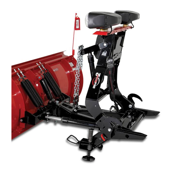
Actual NIGHTHAWK™ Headlamps or confi guration varies by NIGHTHAWK™ LED Headlamps The UltraMount 2 snowplow consists of all the model with EdgeView™ Technology components that are readily removable from the vehicle as a unit. This includes the blade, quadrant, lift frame, A-frame/T-frame, hydraulic unit, and snowplow headlamps. -
Page 19: Blades
It can be touched up when necessary. WESTERN snowplows with poly blades are constructed of a high molecular weight polyethylene Blade guides are included with your complete sheet that is supported with structural steel. -
Page 20: Straight Blades
GETTING TO KNOW YOUR SNOWPLOW Straight Blades DEFENDER™ Compact Plows The reliable, 16-gauge, DEFENDER compact WESTERN straight blades, with their exclusive ® plow features a powder coated steel moldboard Roll-Action™ design, roll snow ahead and to the that is 23½" tall and available in 6'8" and 7'2"... -
Page 21: Hts™ Blades
GETTING TO KNOW YOUR SNOWPLOW steel or ULTRAFINISH™ powder-coated steel. PRO-PLOW Series 2 Blades ® Accessories include: shoe kit, rubber defl ector, Leave it to the pros. Designed to meet the curb guards, 1/2" cutting edge kit, back drag edge requirements of the professional snow plower, kit, poly cutting edge kit. -
Page 22: Pro Plus ® Hd Blades
PRO PLUS performance into the heavy With its deep-curl tapered-wing design, the contractor truck segment with application-specifi c MVP 3 blade takes Western Products' popular UltraMount 2 mounts for most popular Class 4, 5, V-plow design to the next level. Available in 7'6", ®... -
Page 23: Prodigy™ Blades
GETTING TO KNOW YOUR SNOWPLOW PRODIGY™ Blade WIDE-OUT™ & WIDE-OUT™ XL Blades ‡ The WESTERN ® PRODIGY snowplow will The WIDE-OUT and WIDE-OUT XL snowplows automatically confi gure the wings in scoop or provide you the ability to extend the width of... -
Page 24: A-Frame/T-Frame, Quadrant & Lift Frame
GETTING TO KNOW YOUR SNOWPLOW A-FRAME/T-FRAME, QUADRANT, & The hydraulic unit is mounted on the front of the lift frame. The hoses remain connected to LIFT FRAME the hydraulic unit and the rams. The snowplow headlamps are also attached to the lift frame. PRODIGY™, WIDE-OUT™, WIDE-OUT™... -
Page 25: Snowplow Weights
GETTING TO KNOW YOUR SNOWPLOW Snowplow Weights Size Blade Assembly Wt (lb) Wt (kg) Size Blade Assembly Wt (lb) Wt (kg) 6'8" DEFENDER™ 8'–10' WIDE-OUT™* 7'2" DEFENDER 8'–10' WIDE-OUT ‡ 1027 7'6" ENFORCER™ (MS) 8'6"–11' WIDE-OUT™ XL 1197 7'6" ENFORCER 7'6"... -
Page 26: Snowplow Headlamps
The NIGHTHAWK LED snowplow headlamps with EdgeView technology are a set of rectangular Replacement parts are available through your solid-optic LED headlamps with focused low and local WESTERN ® outlet. high beams, combination daytime running lamps (DRLs) and park/turn lights, and blade-edge illumination. -
Page 27: Vehicle Mount
Two removable receiver brackets are attached to the mount using pins and hairpin cotters. The receiver brackets are easily removed to provide Western Products has designed custom mounts more road clearance during the non-plowing for most vehicles. Due to diff erences among months of the year. -
Page 28: Flostat ® Hydraulic System
GETTING TO KNOW YOUR SNOWPLOW FloStat HYDRAULIC SYSTEM ® The HTS™ hydraulic unit has blade scrape lock circuitry built into it. This feature resists a snowplow's tendency to "fl oat up" as large The FloStat hydraulic unit delivers fast and amounts of snow build up in front of the blade uniform speed for lifting and angling. - Page 29 GETTING TO KNOW YOUR SNOWPLOW Straight Blades are raised in approximately The WIDE-OUT™ and WIDE-OUT™ XL blades 3 seconds and angled side to side in are both raised in approximately 3 seconds and approximately 6 seconds. PRODIGY™ blades angled side to side in approximately 2 seconds. are raised in approximately 3 seconds and angled Each wing individually extends and retracts in side to side in approximately 4 seconds.
-
Page 30: System Capacity
GETTING TO KNOW YOUR SNOWPLOW The DEFENDER™ compact plow's hydraulic system ENFORCER™ blades are raised in approximately gives you full control of the snowplow from the 2 seconds and angled side to side in driver's seat. Two single-acting hydraulic rams hold approximately 2 seconds. -
Page 31: Pump Motor Specifi Cations (All Blades)
GETTING TO KNOW YOUR SNOWPLOW Pump Motor Specifi cations HTS™ Blades MVP PLUS™ & MVP 3™ Blades 12V DC with +/– Connection 12V DC with +/– Connection 1600–1700 psi Pump Relief Valve 2200–2300 psi Pump Relief Valve 4000 psi Angling Relief Valve 4550–4650 psi Plowing Relief Valve 7'6", 8'6", &... - Page 32 GETTING TO KNOW YOUR SNOWPLOW PRODIGY™ Blades ENFORCER™ Blades 12V DC with +/– Connection 12V DC with +/– Connection 2200–2300 psi Pump Relief Valve 2200–2300 psi Pump Relief Valve 4000 psi Angling Relief Valve 3400 psi Plowing Relief Valve 4.5" dia 1.5 kW Motor 2200 psi Back Dragging Relief Valve 0.000477 gal/rev Pump 3.0"...
-
Page 33: Cab Controls
The ON/OFF switch on the cab control allows power indicator light will turn OFF. you to turn OFF the control and prevent blade movement even when the ignition switch is ON. WESTERN ® snowplows come equipped with The control ON/OFF switch serves as an one of two special controls: the CabCommand emergency stop, if required. -
Page 34: Prodigy, Defender & Straight Blade Controls
GETTING TO KNOW YOUR SNOWPLOW PRODIGY™, DEFENDER™, & Straight Blade Controls Power Indicator Light (red) ON/OFF Switch (emergency stop) ON/OFF Button (emergency stop) PRODIGY, DEFENDER, & PRODIGY, DEFENDER, & Straight Blade Straight Blade Joystick Control Hand-Held Control Lit. No. 72444, Rev. 05 April 1, 2021... -
Page 35: Mvp Plus, Mvp 3, Enforcer, Wide-Out, & Wide-Out Xl Blade Controls
GETTING TO KNOW YOUR SNOWPLOW MVP PLUS™, MVP 3™, ENFORCER™, WIDE-OUT™, & WIDE-OUT™ XL Blade Controls Power Indicator Light (red) ON/OFF Switch (emergency stop) ON/OFF Button (emergency stop) MVP PLUS, MVP 3, ENFORCER, MVP PLUS, MVP 3, ENFORCER, WIDE-OUT, & WIDE-OUT XL WIDE-OUT, &... -
Page 36: Accessories And Options
ACCESSORIES AND OPTIONS SNOW DEFLECTOR CARBIDE STEEL CUTTING EDGE The optional snow defl ector, available in poly Carbide steel edges provide superior durability (straight blades only) or reinforced rubber, and performance with longer wear compared helps keep snow off the windshield and away to a traditional steel cutting edge. - Page 37 ® www.westernplows.com. DIELECTRIC GREASE Specially formulated dielectric grease protects electrical connections in severe winter conditions. Western Products recommends that snowplow owners apply dielectric grease to all electrical connections on a regular basis. Lit. No. 72444, Rev. 05 April 1, 2021...
-
Page 38: Mounting Snowplow To Vehicle
MOUNTING SNOWPLOW TO VEHICLE MOUNTING SNOWPLOW (ON) NOTE: The blade must be in the straight position when attaching or detaching the DEFENDER™ Compact Plows: snowplow. WARNING NOTE: Use dielectric grease to prevent Keep 8' clear of the blade when it is being corrosion on all connections. - Page 39 MOUNTING SNOWPLOW TO VEHICLE 5. Turn the plow control in the vehicle ON and activate FLOAT mode. Stand Handle 6. Stand in front of the blade. Push the top of the headgear toward the vehicle to allow the connecting pins to fully engage the connecting Stand pin holes.
-
Page 40: Other Blades
MOUNTING SNOWPLOW TO VEHICLE MOUNTING SNOWPLOW (ON) • Remove the electrical plug and disconnect electrical plugs from storage position. Other Blades: • Align the vehicle receiver brackets with the snowplow horns and drive the vehicle slowly WARNING forward until the snowplow horns fully seat Keep 8' clear of the blade when it is being inside the receiver brackets. - Page 41 MOUNTING SNOWPLOW TO VEHICLE 1. After seating the snowplow horns in the receiver brackets, pull the handle up; the shoe will lift off the ground. Handle Receiver Pin (pull) Lock Pin Stand Hook 3. Repeat Steps 1 and 2 on other side of Shoe snowplow.
-
Page 42: Operating Your Snowplow
OPERATING YOUR SNOWPLOW PRODIGY™, DEFENDER™, & Power Indicator FLOAT Light STRAIGHT BLADE Light (red) (green) FLOAT ON/OFF HAND-HELD CONTROL RAISE WARNING ON/OFF Button To prevent accidental movement of the (emergency stop) blade, always push the ON/OFF button to switch the control OFF whenever the snowplow is not in use. - Page 43 OPERATING YOUR SNOWPLOW Automatic Shutdown Function Description of Operation Press this button to raise the blade and RAISE The control will automatically turn OFF after being cancel the FLOAT mode. idle for 20 minutes. To reactivate the control after Press this button to lower the blade. LOWER Release the button to stop the blade at a shutdown, press the ON/OFF button.
- Page 44 OPERATING YOUR SNOWPLOW Function Description of Operation L (Angle Press this button to angle the blade left. Left) R (Angle Press this button to angle the blade right. Right) NOTE: If a control function times out before the desired blade movement is complete, release the button and press it again.
-
Page 45: Joystick Control
OPERATING YOUR SNOWPLOW PRODIGY™, STRAIGHT BLADE, & FLOAT Light Power Indicator DEFENDER™ JOYSTICK CONTROL (green) Light (red) WARNING ON/OFF FLOAT To prevent accidental movement of the blade, always move the ON/OFF switch to RAISE OFF whenever the snowplow is not in use. ON/OFF Switch The power indicator light will turn OFF. - Page 46 OPERATING YOUR SNOWPLOW Function Time-Outs Optional Control Features To limit the amount of electrical energy required The control ships from the factory with the Smooth from the vehicle, all control functions, except Stop feature enabled and the One-Touch FLOAT LOWER/FLOAT, time out (stop) automatically after feature disabled.
- Page 47 OPERATING YOUR SNOWPLOW Control Functions Function Description of Operation Move the control lever toward the top of RAISE, LOWER, FLOAT, Angle RAISE the control body to raise the blade and cancel the FLOAT mode. Move the control lever toward the bottom of Moving the control lever straight up and down or LOWER the control body to lower the blade.
- Page 48 OPERATING YOUR SNOWPLOW SECURITY GUARD™ System (1, 2, 3, 4) Function Description of Operation L (Angle Move the control lever straight to the left Moving the control lever diagonally from Left) to angle the blade left. the center position toward any of the four R (Angle Move the control lever straight to the right digits on the face of the control body will...
-
Page 49: Mvp Plus™, Mvp 3™, Enforcer
OPERATING YOUR SNOWPLOW MVP PLUS™, MVP 3™, ENFORCER™, FLOAT Light Power Indicator WIDE-OUT™, & WIDE-OUT™ XL (green) Light (red) FLOAT ON/OFF BLADES HAND-HELD CONTROL RAISE ON/OFF Button WARNING (emergency stop) To prevent accidental movement of the blade, always push the ON/OFF button to switch the control OFF whenever LOWER the snowplow is not in use. -
Page 50: Control
OPERATING YOUR SNOWPLOW Automatic Shutdown Function Description of Operation Press this button to raise the blade and RAISE The control will automatically turn OFF after being cancel the FLOAT mode. idle for 20 minutes. To reactivate the control after Press this button to lower the blade. a shutdown, press the ON/OFF button. - Page 51 OPERATING YOUR SNOWPLOW SCOOP/RETRACT Blade and Wing Positions Function Description of Operation With wings in a straight line, press the L FLOAT ON/OFF button to move both wings to the angle (Angle left position. The left wing retracts while Left) the right wing extends (MVP PLUS™, RAISE MVP 3™, ENFORCER™).
- Page 52 OPERATING YOUR SNOWPLOW The two round buttons located to the left and right of Function Description of Operation the LOWER button move either wing independently Press this button on the left side of the of the other as described in the following table. control to move the left wing.
-
Page 53: Mvp Plus, Mvp 3, Enforcer, Wide-Out
OPERATING YOUR SNOWPLOW MVP PLUS™, MVP 3™, ENFORCER™, FLOAT Light Power Indicator WIDE-OUT™, & WIDE-OUT™ XL (green) Light (red) BLADES JOYSTICK CONTROL WARNING ON/OFF FLOAT To prevent accidental movement of the RAISE blade, always move the ON/OFF switch to SCOOP RETRACT ON/OFF Switch OFF whenever the snowplow is not in use. - Page 54 OPERATING YOUR SNOWPLOW Function Time-Outs Optional Control Features To limit the amount of electrical energy required The control ships from the factory with the Smooth from the vehicle, all control functions, except Stop feature enabled and the One-Touch FLOAT LOWER/FLOAT, time out (stop) automatically after feature disabled.
- Page 55 OPERATING YOUR SNOWPLOW Control Functions Function Description of Operation Move the control lever toward the top of RAISE, LOWER, FLOAT, Angle RAISE the control body to raise the blade and cancel the FLOAT mode. Move the control lever toward the bottom Moving the control lever straight up and down or LOWER of the control body.
- Page 56 OPERATING YOUR SNOWPLOW Function Description of Operation Function Description of Operation With wings in a straight line, move the Move the control lever toward the word control lever straight to the left to move both SCOOP SCOOP on the control face to extend both (Angle wings to the angle left position.
-
Page 57: Fleet Flex Electrical System
OPERATING YOUR SNOWPLOW FLEET FLEX Electrical System Function Description of Operation Move the control lever toward the left Your UltraMount ® 2 system snowplow comes side of LOWER on the control face. standard with user-controlled programmable The fi rst time the lever is moved into the slot after the control is turned ON or features. -
Page 58: Security Guard™ System
OPERATING YOUR SNOWPLOW SECURITY GUARD™ System 1. Turn the vehicle ignition switch to the "ON" or "ACCESSORY" position. (It is not necessary to start the vehicle.) Activation & Establishing a 4-Digit Security Code 2. Verify that the control power indicator is OFF. If the power indicator light is red, the control is NOTE: The snowplow must be attached to ON. - Page 59 OPERATING YOUR SNOWPLOW 5. After you have entered your 4-digit Manual Unlock Procedure security code, the FLOAT light will stop fl ashing and the power indicator light will If the SECURITY GUARD system is activated turn OFF. This indicates that your 4-digit and you are using a control programmed with a security code is entered and stored in the diff...
- Page 60 OPERATING YOUR SNOWPLOW 4. With the control OFF, move the control lever NOTE: If the plow/vehicle electrical to the #2 position or press the #2 button four connection is lost or disconnected, the consecutive times, then move the lever to SECURITY GUARD™...
- Page 61 OPERATING YOUR SNOWPLOW Light Flash Indicators Additional Notes • The SECURITY GUARD™ system requires POWER – Red Function any control other than the one with the Control is OFF assigned 4-digit security code to enter the security code before the snowplow can Solid ON Control is ON and active be activated.
-
Page 62: Smooth Stop/Soft Stop
OPERATING YOUR SNOWPLOW Smooth Stop/Soft Stop Enable/Disable Procedure 1. Turn the vehicle ignition switch to the "ON" or Smooth stop, or soft stop, allows the blade to "ACCESSORY" position. (It is not necessary coast to a stop when the button/lever is released. to start the vehicle.) The result is smoother operation, reduction in shock to the hydraulic system, and an increase in... -
Page 63: One-Touch Float
OPERATING YOUR SNOWPLOW One-Touch FLOAT Enable/Disable Procedure 1. Turn the vehicle ignition switch to the "ON" or One-touch FLOAT immediately activates the "ACCESSORY" position. (It is not necessary FLOAT mode and releases the blade to the to start the vehicle.) ground, without having to hold the button or lever in LOWER. -
Page 64: V-Plow Blade Positions
OPERATING YOUR SNOWPLOW V-PLOW BLADE POSITIONS Straight Blade NOTE: For best road clearance during Move both wings to form a straight blade for transport, place the blade halfway between wide-path plowing or stacking snow. the straight and retracted (vee) positions. The scoop position is NOT RECOMMENDED during transport. - Page 65 OPERATING YOUR SNOWPLOW Angled Blade Retracted (Vee) Blade Move one wing "OUT" and the other wing "IN" to Move both wings "IN" toward the vehicle for initial form an angled blade in either direction for general break-through plowing and plowing paths or plowing and widening.
- Page 66 OPERATING YOUR SNOWPLOW Scoop Blade Dogleg Blade Move both wings "OUT" away from the vehicle to Move one wing to straight blade position and the form a scoop to carry snow with minimum spilloff . other "OUT" to scoop blade position for clean-up of windrows.
-
Page 67: Prodigy Blade Positions
OPERATING YOUR SNOWPLOW PRODIGY™ BLADE POSITIONS Angled Blade The PRODIGY snowplow can be used in three The wings automatically adjust in and out as the basic plowing positions. blade is angled left or right. Scoop Blade When blade is moved to straight-across orientation, both wings automatically angle into scoop position. - Page 68 OPERATING YOUR SNOWPLOW Straight Blade Option The wings may be pinned in position to operate as 2. Standing behind the blade, install a a straight blade, using the hardware provided: 3/4" x 9" clevis pin down through the holes in the back of the blade assembly, as shown.
-
Page 69: Wide-Out & Wide-Out Xl Blade Positions
OPERATING YOUR SNOWPLOW WIDE-OUT™ & WIDE-OUT™ XL Retracted Blade BLADE POSITIONS Move both wings "IN" to form a straight blade. The WIDE-OUT and WIDE-OUT XL snowplows can be used in four basic plowing positions. NOTE: Always transport the WIDE-OUT and WIDE-OUT XL snowplows with both wings fully retracted. - Page 70 OPERATING YOUR SNOWPLOW Scoop Blade Dogleg Blade Move both wings "OUT" and ahead of the vehicle Move one wing to extended position and the other to form a scoop to carry snow with minimum "OUT" to scoop blade position for clean up of spilloff...
- Page 71 OPERATING YOUR SNOWPLOW Extended Blade Move both wings "OUT" straight for an extra-wide blade for clearing large areas. Lit. No. 72444, Rev. 05 April 1, 2021...
-
Page 72: Snowplow Headlamp Check
OPERATING YOUR SNOWPLOW SNOWPLOW HEADLAMP CHECK Aiming the Headlamps With all electrical plugs connected, check the • Aim the snowplow headlamps with the operation of vehicle and snowplow headlamps. snowplow mounted and raised in the transport position. See "Aiming Headlamp Beams" in Lights Results the Maintenance section for instructions. -
Page 73: Shoe Adjustment
OPERATING YOUR SNOWPLOW SHOE ADJUSTMENT Adjustment Procedure 1. Raise the blade 1 foot off the road surface, WARNING turn the control OFF and, from in front of Blade can drop unexpectedly. Place blade the blade, place jack stands under the on jack stands. - Page 74 OPERATING YOUR SNOWPLOW 6. Reinstall the linchpin. Optional MVP PLUS™, Turn the vehicle ignition to the "ON" position, PRODIGY™, and turn the control ON. Raise the blade WIDE-OUT™, & Shoe slightly from the jack stands. Turn the control WIDE-OUT™ XL Holder OFF, and remove the jack stands.
- Page 75 OPERATING YOUR SNOWPLOW Optional Optional PRO PLUS ENFORCER™ ® Shoe Kit Shoe Kit Shoe Cotter Holder Shoe Washers Actual Holder Spacer confi guration Shoe varies by model. Disc Linchpin Shoe Lit. No. 72444, Rev. 05 April 1, 2021...
-
Page 76: Hydraulic System
OPERATING YOUR SNOWPLOW HYDRAULIC SYSTEM Blade Drop Speed Adjustment Hydraulic Fluid WARNING Keep 8' clear of the blade when it is being For hydraulic fl uid type and fi lling instructions, see raised, lowered, or angled. Do not stand "Annual Fluid Change" under "Hydraulic System" between vehicle and blade or directly in in the Maintenance section of this manual. - Page 77 OPERATING YOUR SNOWPLOW HTS™ Blades: Remove the hydraulic unit cover. Straight Blades: Follow the "Straight Blade Hydraulic Unit Cover – Remove and Replace" procedure in the Maintenance section of this manual. Quill Quill DEFENDER™ Compact Plow Blades: The blade will not drop when quill is fully tightened ENFORCER™...
-
Page 78: Angle Ram Adjustment - Enforcer
OPERATING YOUR SNOWPLOW ANGLE RAM ADJUSTMENT – ENFORCER™ BLADES The ENFORCER V-plow has adjustable angle rams with two possible mounting positions at the base end of each ram, nearest the vehicle. This feature provides a means for making an adjustment in available ground clearance for when the snowplow is fully raised and in full angled or retracted (vee) positions. - Page 79 OPERATING YOUR SNOWPLOW MVP PLUS™, MVP 3™, WIDE-OUT™, to decrease drop speed. Turn the quill OUT WIDE-OUT™ XL, and PRODIGY™ Blades: Lift (counterclockwise) to increase drop speed. the hydraulic unit top cover retainer, remove the 3. Stand 8 feet clear of the blade when checking bottom cover retainer and remove the side cover.
-
Page 80: Transporting The Snowplow
OPERATING YOUR SNOWPLOW TRANSPORTING THE SNOWPLOW NOTE: Always transport the WIDE-OUT™ and WIDE-OUT™ XL snowplows with both wings fully retracted. WARNING Position the blade so it does not block the 1. Completely raise the blade. headlamp beam. Do not change blade position while 2. -
Page 81: Driving And Plowing On Snow And Ice
OPERATING YOUR SNOWPLOW DRIVING AND PLOWING ON SNOW Wet and hard-packed snow or ice off ers the worst tire traction. It is very easy to lose control. You will AND ICE have diffi culty accelerating. If you do get moving, you may have poor steering and diffi... -
Page 82: Plowing Snow
OPERATING YOUR SNOWPLOW PLOWING SNOW • If you are tired, pull off in a safe place and rest. • Keep your windshield and all glass on your WARNING vehicle clean to see around you. Never plow snow with head out the vehicle •... -
Page 83: General Instructions
OPERATING YOUR SNOWPLOW General Instructions CAUTION Never stack snow with the blade angled. 1. Before plowing, make sure that you know This could damage the snowplow or the of any obstructions hidden beneath the vehicle bumper. snow, such as bumper stops in parking lots, curbs, sidewalk edges, shrubs, fences, or pipes sticking up from the ground. -
Page 84: Hard-Packed Snow, Deep Snow
OPERATING YOUR SNOWPLOW Hard-Packed Snow 2. Bite into the edges using only partial blade width until the job is cut down to size for full-blade plowing. 1. Raise the disc shoes so that the cutting edge comes into direct contact with the pavement. Rule of thumb: 6"... -
Page 85: Clearing Driveways, Parking Lots
OPERATING YOUR SNOWPLOW Clearing Driveways Clearing Parking Lots 1. Head into the driveway with the blade angled 1. Clear areas in front of buildings fi rst. With the and plow the snow away from any buildings. blade raised, drive up to the building. Drop Widen the driveway by rolling snow away from the blade and back drag the snow away from any buildings. -
Page 86: Parking With Snowplow Attached
OPERATING YOUR SNOWPLOW PARKING WITH SNOWPLOW TOWING A DISABLED OR STUCK ATTACHED VEHICLE Do not use any snowplow components as an WARNING attachment point when retrieving, towing, or Lower the blade when the vehicle is winching a disabled or stuck vehicle. parked. -
Page 87: Removing Snowplow From Vehicle & Storage
REMOVING SNOWPLOW FROM VEHICLE & STORAGE REMOVING SNOWPLOW (OFF) CAUTION Store PRO PLUS , PRO PLUS ® ® WARNING PRO-PLOW Series 2, MIDWEIGHT™, and ® PRODIGY™ A-frame in a horizontal position. Keep 8' clear of the blade when it is being This will prevent water from collecting and raised, lowered, or angled. - Page 88 REMOVING SNOWPLOW FROM VEHICLE & STORAGE 6. DEFENDER™ Compact Plows: Pull the CAUTION stand lock pin out and let the stand drop to On 2-plug electrical systems, plug covers the ground. Release the stand lock pin. Verify shall be used whenever snowplow is that the stand is locked by trying to lift the disconnected.
- Page 89 REMOVING SNOWPLOW FROM VEHICLE & STORAGE Removing DEFENDER™ Compact Plow Stand Handle Stand Stand Lock Pin Receiver Notch Connecting Pin Receiver Connecting Blade Rear Locking Headgear Receiver Hole Slot Stand Connecting Pin Hole Lit. No. 72444, Rev. 05 April 1, 2021...
- Page 90 REMOVING SNOWPLOW FROM VEHICLE & STORAGE Other Blades: Pull and hold the lock pin out, then rotate the handle DOWN and release the lock pin. It must lock into the LOWER hole. Handle Receiver Pin Shoe Handle (pull) Lock Pin 9.
-
Page 91: Maintenance
MAINTENANCE Snowplow Not Attached to Vehicle Hairpin Cotters Washer Washer 1. Tilt the lift frame forward to create slack in the lift chains. On the driver-side lift chain, mark the link attaching it to the lift arm. 2. Unhook the driver-side lift chain from the lift DS Lift arm, remove the slack, and hook the chain Chain... -
Page 92: Maintenance Videos
MAINTENANCE MAINTENANCE VIDEOS • Clean and tighten all electrical connections and coat with dielectric grease. Video demonstrations of several snowplow • Check hydraulic system for leaks and cracked maintenance tasks, including "Preseason Plow or damaged hoses. Maintenance" and "Annual Fluid Change," are available under the Support heading at •... -
Page 93: Postseason Maintenance
See your authorized WESTERN outlet for service. ® • Lubricate all pivot points (for example, the stand lock pin assembly and lower spring anchor) with general purpose petroleum grease. -
Page 94: Aiming Headlamp Beams
MAINTENANCE AIMING HEADLAMP BEAMS 1. Prepare the vehicle for headlamp aim or inspection. Before checking beam aim, the inspector will: Tighten headlamp fasteners to 22 ft-lb, or 30 N·m, once correct visual aim is achieved. a. Remove ice or mud from under fenders. b. - Page 95 MAINTENANCE 2. Mark (or tape) the vertical centerline of 3. Align the top edge of the high-intensity zone the snowplow headlamps and the vertical of the snowplow lower beam below the centerline of the vehicle on the screen. Mark horizontal centerline and the left edge of the the horizontal centerline of the snowplow high-intensity zone on the vertical centerline headlamps on the screen (distance from...
-
Page 96: Changing Blade-Edge Illumination Mode
MAINTENANCE CHANGING BLADE-EDGE Remove the jumper fuse from the fuse holder and re-insert it in the desired mode position as ILLUMINATION MODE shown below. Replace the fuse holder cover. On snowplows equipped with NIGHTHAWK™ LED Jumper headlamps, the EdgeView™ technology feature Fuse off... -
Page 97: Straight Blade Hydraulic Unit Cover
MAINTENANCE STRAIGHT BLADE AND Hairpin Cotters ENFORCER™ HYDRAULIC UNIT Washer Washer COVER – REMOVE AND REPLACE Snowplow Attached to Vehicle 1. Lower the blade to the ground. Place the control in FLOAT, fully collapsing the lift ram. Turn the control OFF. Lift Frame 2. -
Page 98: Maintenance And Adjustment
Pivot Bolt components. Failure to do this could result in serious personal injury. Your WESTERN ® snowplow is designed for rugged, dependable service. However, like the vehicle on which it is mounted, it needs regular 3. -
Page 99: Greasing Pivot Pin Hinge
When the proper tension is reached, tighten the locknut. Blade Finish: If the powder-coat fi nish is nicked or scratched, repair the surface and paint with WESTERN red or black paint ® Grease the hinge at the beginning of the (available in aerosol or quart can). -
Page 100: Cutting Edge Wear And Leveling Adjustment
MAINTENANCE CUTTING EDGE WEAR AND 2. Vehicle and snowplow must be on a level surface. LEVELING ADJUSTMENT 3. If the optional shoe kit has been installed on the blade, remove the shoes during this WARNING adjustment procedure. Keep 8' clear of the blade when it is being raised, lowered, or angled. - Page 101 MAINTENANCE 6. Select the hole in the rear of the T-frame Raise and lower the blade several times. The that is best aligned with the rear hole in the cutting edge should be contacting the level pushbeam and reinstall the rear fasteners. surface across the full length of the cutting Tighten all four fasteners to 250 ft-lb.
-
Page 102: Prodigy™ Wing Cutting Edges
MAINTENANCE PRODIGY™ Wing Cutting Edges WARNING Keep 8' clear of the blade when it is being Loosen inner raised, lowered, or angled. Do not stand fasteners. between vehicle and blade or directly in front of blade. If the blade hits or drops on you, you could be seriously injured. -
Page 103: Hydraulic System Maintenance
MAINTENANCE HYDRAULIC SYSTEM MAINTENANCE 2. For PRODIGY™ and straight blades any angle will do, but for MVP PLUS, MVP 3, ENFORCER, WIDE-OUT, and WIDE-OUT XL Fluid Level blades, move the blade wings to the fully retracted (vee) position. CAUTION 3. Activate the control FLOAT function and Do not mix diff... - Page 104 MAINTENANCE 5. Remove the fi ll plug. Straight Blades, ENFORCER™, MVP PLUS™, MVP 3™, WIDE-OUT™, 6. HTS™ Blades: Fill the reservoir to within WIDE-OUT™ XL, and PRODIGY™ Blades: 2-1/2" from the top of the fi ll hole and replace Fill the reservoir to the top of the fi ll hole and the fi...
-
Page 105: Annual Fluid Change
MAINTENANCE Annual Fluid Change Perform this operation with the snowplow attached to the vehicle on a hard, level surface. WARNING 1. Lower the blade to the ground. For PRODIGY™ Blades, move the blade to the Keep 8' clear of the blade when it is being scoop position so wings are forward. - Page 106 (vee) position. With the lift on the hydraulic unit and place them in a drain ram fully retracted, fi ll the reservoir with pan or suitable container. See the following WESTERN High Performance Hydraulic ® Hose Routing Diagrams and refer to the Fluid rated to –40°F (–40°C), or other...
-
Page 107: House Routing Diagrams
MAINTENANCE Hose Routing Diagrams HTS™ Blades Straight Blades To PS Angle Ram To Lift Ram Base To DS Angle Ram To DS Angle To PS To Lift Angle Ram Ram Rod To Lift Ram Lit. No. 72444, Rev. 05 April 1, 2021... - Page 108 MAINTENANCE Hose Routing Diagrams, continued ENFORCER™ Blades MVP PLUS™ To DS Rod (front) To Lift Ram To DS Base PS Ram (rear) Rod End PS Ram Base End Lift DS Ram Base End To PS Base To PS Rod DS Ram (rear) (front) Rod End...
- Page 109 MAINTENANCE Hose Routing Diagrams, continued WIDE-OUT™ & MVP 3™ PRODIGY™ WIDE-OUT™ XL To DS Rod To DS (front) Wing Rod To DS To DS Wing To DS To Lift Angle Base Base To DS To PS Base Angle (rear) (rear) To Lift To PS Angle Ram...
- Page 110 MAINTENANCE Remove air from the system. Follow the steps d. Add more fl uid as needed. under the heading for the correct blade model: PRODIGY and Straight Blades: Fill the reservoir to the top of the fi ll hole and Air Removal –...
- Page 111 MAINTENANCE Air Removal – MVP PLUS™, MVP 3™, and d. Turn the control ON and raise and lower ENFORCER™ Blades the snowplow several times. Activate the control FLOAT function and manually a. Turn the control ON and completely collapse the lift ram all the way after each extend and retract the driver-side wing lowering of the blade.
-
Page 112: Air Removal
MAINTENANCE Air Removal – WIDE-OUT™ & c. Turn the control ON. Angle blade fully WIDE-OUT™ XL Blades left and right and raise and lower the snowplow several times. Activate the a. Turn the control ON and completely control FLOAT function and manually extend and retract the driver-side collapse the lift ram all the way after each wing several times. -
Page 113: Hose Or Fitting Replacement
MAINTENANCE Hose or Fitting Replacement 2. Lower the snowplow completely and turn the control OFF. WARNING NOTE: Loosen the fi ll plug slowly to relieve Lower the blade when the vehicle is any pressure in the reservoir. parked. Keep 8' clear of the blade. Temperature changes could change 3. -
Page 114: Installing Hydraulic Fittings And Hoses
MAINTENANCE Installing Hydraulic Fittings and Hoses 5. Using a wrench and pliers, hold the fi tting body in position and tighten the jam nut until the washer again contacts the port face, then NOTE: Overtightening JIC hose fi tting ends tighten an additional 1/8 to 1/4 turn to lock the will result in a fractured fi... -
Page 115: Fuse Replacement
MAINTENANCE FUSE REPLACEMENT The ENFORCER™ hydraulic unit harness system contains one 5A fuse in the 3-coil port C harness, and two 5A fuses in the 4-coil port B harness. The vehicle control harness contains two automotive-style fuses. The snowplow park/turn The PRODIGY™, HTS™, and straight blade power and control power are covered by individual hydraulic unit harness systems contain two... -
Page 116: Snowplow Vehicle Battery Best Practices
MAINTENANCE SNOWPLOW VEHICLE BATTERY • Avoid leaving the snowplow vehicle parked (unused) for three weeks or longer. BEST PRACTICES • Parking a vehicle with the battery in a • Keep all battery connections tight and clean. discharged state can result in permanent Poor connections cause higher power battery damage. -
Page 117: Vehicle
WESTERN red or black paint ® • Electrical tape in aerosol or quart cans from your WESTERN outlet. Clean and repaint parts as necessary. Always use WESTERN designed and tested replacement parts. Lit. No. 72444, Rev. 05... -
Page 118: Troubleshooting
Parts Lists, Mechanic's Guides, and service information to assist the qualifi ed mechanic with repair. Western Products does not recommend repairs by other than our factory-trained outlets. Failure to use an authorized outlet could aff ect the warranty coverage on your snowplow. -
Page 119: Appendix
3.25 3.25 3.75 3.25 3.75 3.25 WIDE-OUT™ XL Snowplow 3.25 3.25 3.75 3.25 3.75 3.25 WESTERN Joystick Control PRODIGY Straight Blades DEFENDER Compact Plow MVP Plus Snowplow MVP 3 Snowplow ENFORCER Snowplow WIDE-OUT Snowplow 3.25 3.25 3.75 3.25 3.75 3.25 WIDE-OUT XL Snowplow 3.25... - Page 120 Copyright © 2021 Douglas Dynamics, LLC. All rights reserved. This material may not be reproduced or copied, in whole or in part, in any printed, mechanical, electronic, fi lm, or other distribution and storage media, without the written consent of Western Products.
Need help?
Do you have a question about the UltraMount 2 and is the answer not in the manual?
Questions and answers
the pump comes on but nothing will move, control and lights all seam to be working, will not move left or right or up or down?
If the Western UltraMount 2 pump activates but does not move left, right, up, or down, possible issues could include:
1. Hydraulic Fluid Level – Check if the fluid reservoir is properly filled. If it is low or empty, the system may not function correctly.
2. Hydraulic System Blockage – Ensure there are no clogs in the hydraulic lines or valves that could prevent movement.
3. Electrical Connection Issues – Inspect the wiring, connectors, and CAN communication bus for any loose or faulty connections.
4. Control System Malfunction – Verify that the control is functioning properly and sending the correct signals.
5. Faulty Solenoid or Valve – If a solenoid or valve is not working, it may prevent hydraulic movement.
Checking these components should help diagnose and resolve the issue.
This answer is automatically generated