
Related Manuals for norbar PNEUTORQUE PTS-52-500


Summary of Contents for norbar PNEUTORQUE PTS-52-500
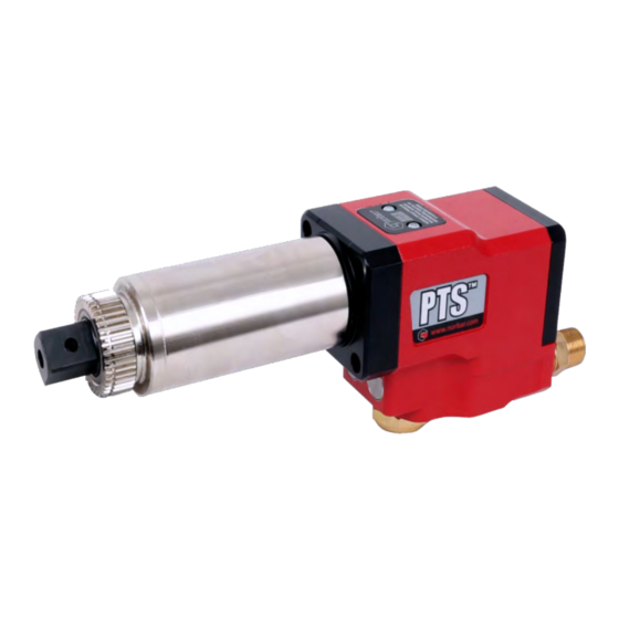
- Page 1 OPERATOR’S MANUAL PNEUTORQUE ® PTS™ 500/800/1000/1350/2000/2700/4000/7000 REMOTE CONTROL AIR MOTOR Part Number 34442 | Issue 1 | Original Instructions (English)
-
Page 3: Table Of Contents
CONTENTS Part Numbers Covered by This Manual Safety Introduction Parts Included Explanation of Data Label Accessories Features and Functions Set up Instructions 1. Torque Reaction 2. Air Lubrication 3. Tool Control Systems 4. Input Ports 5. Exhaust Port 6. Setting Torque for Fastener Tightening Operating Instructions Tightening Releasing... -
Page 4: Part Numbers Covered By This Manual
PART NUMBERS COVERED BY THIS MANUAL This manual covers all PTS™ series remote control tools, including the following: Part Number Model Direction Maximum Torque 180271.B06 PTS™-52-500 Bi-directional 500 N·m 180272.B06 PTS™-52-800 Bi-directional 800 N·m 180273.B06 PTS™-72-1000 Bi-directional 1000 N·m 180274.B08 PTS™-72-1350 Bi-directional 1350 N·m... -
Page 5: Safety
SAFETY IMPORTANT: THIS OPERATOR’S MANUAL SHOULD BE KEPT FOR FUTURE REFERENCE. General Safety Rules: • For multiple hazards, read and understand the safety instructions before installing, operating, repairing, maintaining, changing accessories on, or working near the assembly power tool for threaded fasteners. Failure to do so can result in serious bodily injury. - Page 6 • Maintain a balanced body position and secure footing. • Release the trigger in the case of an interruption of the energy supply. • Use only lubricants recommended by the manufacturer. • Do not use in confined spaces and beware of crushing hands between tool and workpiece. Repetitive Motions Hazards: •...
- Page 7 Noise Hazards: • Unprotected exposure to high noise levels can cause permanent, disabling, hearing loss and other problems, such as tinnitus (ringing, buzzing, whistling or humming in the ears). Therefore a risk assessment and implementation of appropriate controls for these hazards are essential. •...
- Page 8 Pictograms on Tool Meaning Read and understand Operator’s Manual. If a Reaction is purchased from Norbar it will include this label: Unexpected tool movement due to reaction forces or breakage of drive square or reaction bar may cause injuries. There is a risk of crushing between the reaction bar and workpiece.
-
Page 9: Introduction
USB drive Explanation of Data Label: FIGURE 1 – Data Label Norbar Serial Number (First 4 digits = Year of manufacture). Norbar Part Number, including reference to square drive size. Maximum calibrated Torque value. Maximum rated air pressure. Maximum free-running speed (achieved when tool is set to the air pressure for the max. torque value). -
Page 10: Accessories
Accessories Part Number Description PTS™-52 PTS™-72 PTS™-80 PTS™-92 PTS™-119 Lubro Control Unit 16074 16074 16074 16074 16074 18544 18779 ¾” Drive Square (fixing screw) (25351.30) (25352.45) 18545 18492 18934 1” Drive Square (fixing screw) (25351.30) (25352.45) (25352.60) 18935 18959 1 ½” Drive Square (fixing screw) (25352.60) (25352.80) - Page 11 Part Number Description PTS™-52 PTS™-72 PTS™-80 PTS™-92 PTS™-119 (¾”) (¾”) 19046.012 (1”) 12” Splined Nose Extension 19045.012 (1”) 19047.012 19285.012 Lifting Handle 19363 19363 19363 19363 Lightweight Aluminium Reaction 18961 18494 18936 [NOTE 2] Standard Steel Reaction 18646 19289 19289 19291 19293 Twin Solenoid Valve...
-
Page 12: Features And Functions
Models covering 8 torque ranges from 500 N·m up to 7000 N·m. • Wide range of compatible tool controllers and solenoid valves. • Wide range of transducers available. • Norbar’s in-house ‘Engineer-to-Order’ team offer customised / integrated design solutions featuring the PTS™ Remote. -
Page 13: Set Up Instructions
The remote control tools are not supplied with a reaction plate/bar as standard. Norbar offer several types of reaction bar (like the double-sided reaction plate shown in Figure 4) and weld rings (figure 3) which allow users to integrate the reaction spline into their own custom reaction solutions. -
Page 14: Air Lubrication
Standard drive square extensions MUST NOT be used as these will cause serious damage to the tool output drive. A range of nose extensions is available for applications where access is restricted. These are designed to support the final drive correctly. When the PneuTorque is in operation the reaction plate rotates in the opposite direction to the output drive ®... -
Page 15: Input Ports
2 position, 3 port, capable of plowing 19 l/s, Lubro Control Unit Lubro Control Unit Norbar Remote Motor Typical air pilot ½” BSP spring return valve. 2 position, 3 port, capable of plowing 19 l/s, FIGURE 7 – Example of Pneumatic Circuit Typical air/electric pilot ½”... -
Page 16: Exhaust Port
5. Exhaust Port The exhaust port, located under the tool, is common to both inlet ports. If required an exhaust hose can be connected, this will reduce the sound pressure level. The exhaust hose size must not be reduced from ¾” (19mm) or the tool performance will be reduced. -
Page 17: Operating Instructions
OPERATING INSTRUCTIONS WARNING: KEEP HANDS CLEAR OF THE REACTION BAR AND DRIVE SOCKET. WARNING: WHEN USING THIS TOOL IT MUST BE SUPPORTED AT ALL TIMES IN ORDER TO PREVENT UNEXPECTED RELEASE IN THE EVENT OF FASTENER OR COMPONENT FAILURE. WARNING: CHANGING THE AIR PRESSURE AFTER SETTING THE PRESSURE REGULATOR WILL CHANGE THE STALL TORQUE VALUE. -
Page 18: Maintenance
Any other maintenance or repairs should be carried out by Norbar or a Norbar approved distributor. Maintenance intervals will depend on the tool usage and the environment in which it is being used: •... -
Page 19: Drive Square
Fit new screw and tighten between 4 N·m to 5 N·m (for PTS™-52) or 8 N·m to 9 N·m (for PTS™- 72/80/92/119). Connect air supply. TIP: If the drive square fails continually then seek advice from Norbar or a Norbar approved distributor. Calibration To maintain the PneuTorque accuracy it is recommended the tool is recalibrated every 10,000 cycles or ®... -
Page 20: Specifications
SPECIFICATIONS Torque Part Square Output Model Number Drive Speed Minimum Maximum 180271.B06 PTS™-52-500 ¾” 100 N·m (74 lbf·ft) 500 N·m (370 lbf·ft) 27.8 rev/min 180272.B06 PTS™-52-800 ¾” 160 N·m (118 lbf·ft) 800 N·m (590 lbf·ft) 20.1 rev/min 180273.B06 PTS™-72-1000 ¾” 200 N·m (147 lbf·ft) 1000 N·m (738 lbf·ft) 16.0 rev/min... - Page 21 Repeatability: ±3% Accuracy: Accuracy better than ±3% (see calibration certificate) Operating Range: 20% to 100% of tool capacity Air Consumption: 16.5 l/s (35 CFM) Temperature Range: 0°C to +50°C (operating). -20°C to +60°C (storage). Operating Humidity: 85% Relative Humidity @30°C maximum. Handle Vibration: <...
-
Page 23: Trouble Shooting
TROUBLE SHOOTING The following is only a guide, for more complex faults please contact your local Norbar distributor or Norbar directly. Problem Likely Solutions Check air supply is functioning & connected Check air pressure setting (at least 1 bar) Tool output does not rotate when control system... - Page 24 Tel + 61 (0)8 8292 9777 Tel + 86 21 6145 0368 Email enquiry@norbar.com.au Email sales@norbar.com.cn NORBAR TORQUE TOOLS INC NORBAR TORQUE TOOLS INDIA PVT. LTD 36400 Biltmore Place, Willoughby, Plot No A-168, Khairne Industrial Area, Ohio, 44094 Thane Belapur Road, Mahape, Navi Mumbai –...
Need help?
Do you have a question about the PNEUTORQUE PTS-52-500 and is the answer not in the manual?
Questions and answers