Table of Contents
Advertisement
Quick Links
Advertisement
Chapters
Table of Contents

Summary of Contents for Bike-Lift LEB-50 LIFT
- Page 1 EC Use and Maintenance Manual LIFT Model LEB-50 Bike-Lift EUROPE s.r.l. via Don Milani, 40/42 – 43012 Sanguinaro di Fontanellato (PARMA) Italy Website: www.bikelifteurope.it E-mail: info@bikelifteurope.it Operating manual No. 057-2-6-0015-R0 P. 1 Version 2021...
-
Page 2: Table Of Contents
Summary Information section ..........................4 1.1 Preface ............................... 4 1.2 Prohibitions ............................5 1.3 Warranty ............................5 1.3.1 Warranty conditions ........................5 1.3.2 Insurance ........................... 5 1.4 Manufacturer identification ......................6 1.5 Technical assistance and spare parts ....................6 1.6 CE Declaration of conformity ......................7 1.7 Normative references ........................ - Page 3 Commissioning ..........................20 Dismantling/scrapping section ......................21 Dismantling ............................21 Mechanical dismantling ........................21 Scrapping ............................21 Operation section ..........................22 Loading operations .......................... 23 Unloading operations ........................24 Maintenance section ........................25 Lubrication ............................25 Cleaning ............................25 8.2.1 Initial cleaning ..........................
-
Page 4: Information Section
Information section 1.1 Preface The EC Use and Maintenance Manual is a document issued by Bike-Lift Europe s.r.l. as an integral part of the Machine. The purpose of this publication is to provide the operator with efficient and safe instructions regarding the use and maintenance operations. -
Page 5: Prohibitions
It also becomes void if the product has been submitted to performances exceeding those indicated by Bike-Lift Europe srl. 1.3.2 Insurance All Bike-Lift products are insured with an RCP policy with a price ceiling of € 3.000.000. Damages caused by negligence or tampering are excluded. Operating manual No. 057-2-6-0015-R0 P. -
Page 6: Manufacturer Identification
WARNING: THE RECIPIENT WILL BE CHARGED FOR THE REPLACEMENT TOGETHER WITH THE SHIPPING COSTS. We recommend that you always contact Bike-Lift Europe s.r.l. for all those Assistance and maintenance operations that are not described or indicated in this Manual. Operating manual No. 057-2-6-0015-R0 P. -
Page 7: Ce Declaration Of Conformity
1.6 CE Declaration of conformity (Annex II, part 1, section A of directive 2006/42/EC) Manufacturer: Company: Bike-Lift EUROPE S.r.l. Address: Via Don Milani, 40/42 - 43012 Sanguinaro di Fontanellato (PR) - Italy Declares under its sole responsibility that the machine:... -
Page 8: Normative References
1.7 Normative references The machine is identified by the CE marking drawn up according to the specifications of the Machinery Directive 2006/42/EC and subsequent amendments. Reference Title 2006/42/EC Machinery Safety Directive 2014/30/EC Electromagnetic Compatibility Directive (EMC) 2014/35/EU Low Voltage Directive (LVD) Safety of machinery - General principles of design EN ISO 12100:2010 - Risk assessment and risk reduction. -
Page 9: Key
1.8 Key LIFT: Electrical handling system for bicycles maintenance and repair. The specific identification of the lift is indicated on the cover. OPERATOR: In compliance with Directive 2006/42/EC and subsequent amendments, it is specified that the term "operator" means the person(s) in charge of installing, operating, adjusting and cleaning the lift. -
Page 10: Machine Description
Machine description 2.1 Machine name Lift for the maintenance and repair of bicycles and E-Bikes with a maximum capacity of 50 kg. Bike Lift lifts are handled by an electrical system. This manual refers to the lift model indicated on the cover. 2.2 Machine identification Figure 1 - Example of a plate affixed to the machine The identification data of the machine is indicated on the plate placed on the structure and... -
Page 11: Machine Description
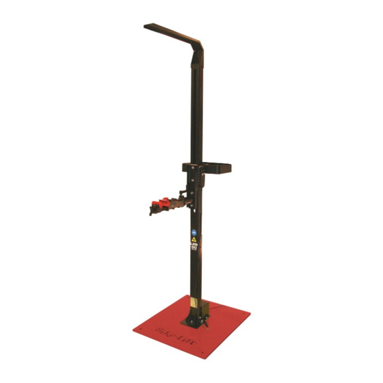
2.3 Machine description The machine known as LEB-50 Lift is a suitable equipment for lifting bicycles during the maintenance and repair phase in a comfortable and safe way. The basic parts of the lift are: – Figure 2 Main components of the lift 1. -
Page 12: Intended Use
The experience of Bike-Lift EUROPE s.r.l. allows you to report beforehand the following cases of misuse for which it is not possible to use the machine:... -
Page 13: Technical Specifications
The following cases are considered a misuse: Operating the machine without having read and understood the instructions provided by the manufacturer Bike-Lift EUROPE s.r.l. Performing operations for which no information was provided by the manufacturer Bike-Lift EUROPE s.r.l. -
Page 14: Safety Section
Safety section 3.1 Environmental working values The use environment of the machine must be well lit, must not present explosion hazards of any kind and must be protected from atmospheric precipitation. The machine works properly within the following values: Ambient temperature between 5° and 40° C; ... -
Page 15: Operator Protections
Finally, we remind you that the handling, installation, use, maintenance and decommissioning of the machine represent a source of hazard if these operations are not performed in compliance with the requirements of this Manual or without the necessary caution and attention required. -
Page 16: Transport And Handling
Transport and handling section 4.1 Transport, handling and storage WARNING: Disseminate the instructions described in this chapter to all personnel involved in the transport and handling of the machine. For safety reasons, the moving parts must be locked before transport. 4.2 Packaging and transport The machine is supplied with two cardboard packaging placed on a wooden pallet. -
Page 17: Storage
Open the box by cutting the clips and the closing adhesive tape. Make sure all the material shown on the delivery note is actually present. Make sure the parts of the machine have not been damaged during transport and notify any damage to the Carrier by REGISTERED LETTER within 5 days of receipt (and notify Bike Lift Europe s.r.l.), by attaching photographic evidence. -
Page 18: Installation Section
Installation section The machine must be installed in compliance with the safety regulations and instructions included in this chapter. The machine does not need a base, but requires a flat and horizontal floor. The floor must be able to support the load of the machine. The bicycle lift must be placed in such a way as to allow the Operator to easily repair bicycles. -
Page 19: Power
Fix the base to the floor using dowels. Fix the two screws of the engine casing (Figure 3, [2]). Before fixing the casing, make sure that the actuator is positioned inside the casing. Insert the two screws to fix the vice to the pole plate (Figure 4, [1]) ... -
Page 20: Commissioning
5.3 Commissioning The tests to be carried out before using the machine have the task of checking that the mechanical and electrical installation has been carried out correctly and there are no breakages or damages that could compromise the proper functioning and the performance of the machine. -
Page 21: Dismantling/Scrapping Section
Dismantling/scrapping section 6.1 Dismantling Follow the materials dismantling Regulations in force in the country where the machine will be dismantled. Here are some useful indications in case you must disassemble the machine to reassemble it in other areas, store it or dismantle it. 6.2 Mechanical dismantling Before proceeding with the mechanical dismantling of the machine it is necessary to disconnect the machine from the electric mains and thoroughly clean the entire structure (see... -
Page 22: Operation Section
Operation section – Figure 6 Operation of the lift – Figure 7 Detail of the adjustable handbar lock Operating manual No. 057-2-6-0015-R0 P. 22 Version 2021... -
Page 23: Loading Operations
7.1 Loading operations 1- Make sure that the power cable is connected to the mains and that the vice (Figure 6, [1]) is in the low position; 2- Move the bicycle closer to the lift and insert the seatpost in the vice. 3- Tighten the vice by turning the handle (Figure 6, [2]);... -
Page 24: Unloading Operations
7.2 Unloading operations 1- Press and hold down the arrow on the control panel; 2- Once the lowest height is reached, release the button. The lift stops automatically. 3- Release the steering wheel lock; 4- Open the vice and remove the bicycle; 5- When you remove the bicycle, place it in a horizontal position to avoid damage. -
Page 25: Maintenance Section
Maintenance section The maintenance operation is the absolute prerogative of professional operators and specialized technicians, in compliance with requirements of Machinery Directive 2006/42/EC and subsequent updates. As routine maintenance, the following checks/operations must be carried out once a month: Visually check the entire machine to make sure that the structures are not deformed or ... -
Page 26: General Cleaning Of The Machine
8.2.2 General cleaning of the machine Perform the general cleaning of the machine weekly with the utmost care. Remove foreign substances: you can use non-corrosive detergents for ferrous and rubber material. These detergents must not be harmful to the operator (follow the instructions contained in the safety data sheets of the substances used, also for the selection of personal protective equipment worn by the operator during work). - Page 27 – Figure 9 Actuator dismantling Operating manual No. 057-2-6-0015-R0 P. 27 Version 2021...
-
Page 28: Problems And Solutions
When implementing the suggested remedy, always follow the instructions described in the Instructions section to which the remedy refers. Bike-Lift Europe s.r.l. will solve all the problems that cannot be eliminated by means of the annexed instructions. PROBLEM... -
Page 29: Accessories
Accessories Operating manual No. 057-2-6-0015-R0 P. 29 Version 2021... -
Page 30: Spare Parts - Technical Drawings
SPARE PARTS - TECHNICAL DRAWINGS Operating manual No. 057-2-6-0015-R0 P. 30 Version 2021... -
Page 31: Electric Actuator Manual
ELECTRIC ACTUATOR MANUAL Operating manual No. 057-2-6-0015-R0 P. 31 Version 2021... - Page 32 LINEAR ACTUATOR Operating Manual Version Date Version 2019.09.27 VER 1.0 - 1 -...
- Page 33 Catalogue 1、Overview 2、Product Type: 3、Product Specification Table 4、Dimensional Drawing 5、Use Installation Instructions 6、Notice for usage - 2 -...
-
Page 34: 1、Overview
1、 Overview Linear Actuator DS-M05 ● Rating Voltage:24 V DC ● Max Load:500N ● Max Speed:30mm/s ● Stroke:813mm ● Protection Class:IP43 DS-M05 has a low noise level, large load capacity。 Because of its compact design, it has a more convenient installation. -
Page 35: 2、Product Type
2、 Product Type: DS M Product Code Product Series Company Code - 4 -... -
Page 36: 3、Product Specification Table
3、 Product Specification Table Serial Items Unit Specification Remark Number Electrical Specification 1.1 Rating Voltage DC24V 1.2 No-load Current <1A 1.3 Rating Current 3.5 A 1.4 Rating Power Load Capacity 500N (push) 2.1 Max Load Capacity 500N (pull) 2.2 Static Load 500N (max) Running Speed 3.1... -
Page 37: 4、Dimensional Drawing
4、Dimensional Drawing - 6 -... -
Page 38: 5、Use Installation Instructions
5、Use Installation Instructions A. Circlip B. Install the shackles C. Axis pin D. Riser head E. U shackles - 7 -... -
Page 39: 6、Notice For Usage
6、Notice for usage 6.1 Only for indoor use 6.2. Keep in dry air 6.3 Ambient temperature: -15℃ to +45℃ 6.4 Duty cycle: 10%, 2 minutes at continuous use followed by an 18 minutes pause。 6.5 When the linear actuator is used, the load capacity cannot be over the max capacity as mentioned. - Page 40 NOTES...
- Page 41 NOTES...
- Page 42 Bike-Lift EUROPE s.r.l. via Don Milani, 40/42 – 43012 Sanguinaro di Fontanellato (PARMA) Italy Website: www.bikelifteurope.it E-mail: info@bikelifteurope.it...
Need help?
Do you have a question about the LEB-50 LIFT and is the answer not in the manual?
Questions and answers