Table of Contents
Advertisement
Quick Links
CHAPTER 1 - INTRODUCTION . . . . . . . . . . . . . . . . . . . . . . . . . . . . . . . . . . . . . . . . .
FUNCTIONAL DESCRIPTION . . . . . . . . . . . . . . . . . . . . . . . . . . . . . . . . . .
1.1
THEORY OF OPERATION . . . . . . . . . . . . . . . . . . . . . . . . . . . . . . . . . . . . .
1.2
CHAPTER 2 - BASIC OPERATION . . . . . . . . . . . . . . . . . . . . . . . . . . . . . . . . . . . . . .
FRONT PANEL INDICATORS AND SWITCHES . . . . . . . . . . . . . . . . . .
2.1
REAR PANEL CONNECTORS . . . . . . . . . . . . . . . . . . . . . . . . . . . . . . . . . .
2.2
CLOCKING, INTERNAL AND EXTERNAL . . . . . . . . . . . . . . . . . . . . . . .
2.3
RS-232 ELECTRICAL INTERFACE . . . . . . . . . . . . . . . . . . . . . . . . . . . . . .
2.4
SUBCHANNEL SERVICE MODES . . . . . . . . . . . . . . . . . . . . . . . . . . . . . .
2.5
ANTI-STREAMING . . . . . . . . . . . . . . . . . . . . . . . . . . . . . . . . . . . . . . . . . . .
2.6
2.7
SYNC AND ASYNC SELECTION . . . . . . . . . . . . . . . . . . . . . . . . . . . . . . .
MANUAL DTE/DCE REMOVAL . . . . . . . . . . . . . . . . . . . . . . . . . . . . . . . .
2.8
2.9
UNEXPLAINED STREAMING TERMINALS . . . . . . . . . . . . . . . . . . . . . .
CASCADING OR CONCATENATION . . . . . . . . . . . . . . . . . . . . . . . . . .
2.10
ENABLE CONTROL (PORTS 1 - 4) . . . . . . . . . . . . . . . . . . . . . . . . . . . . .
2.11
2.12
DCE / DTE SWITCHES . . . . . . . . . . . . . . . . . . . . . . . . . . . . . . . . . . . . . . .
2.13
CHAPTER 3 - INSTALLATION . . . . . . . . . . . . . . . . . . . . . . . . . . . . . . . . . . . . . . . . . .
INPUT VOLTAGE . . . . . . . . . . . . . . . . . . . . . . . . . . . . . . . . . . . . . . . . . . . .
3.1
VOLTAGE FUSES . . . . . . . . . . . . . . . . . . . . . . . . . . . . . . . . . . . . . . . . . . . .
3.2
POWER / GROUND CONNECTION . . . . . . . . . . . . . . . . . . . . . . . . . . . . .
3.3
DEFAULT CONFIGURATION SWITCH SETTINGS . . . . . . . . . . . . . . . .
3.4
MODEM (DCE) AND TERMINAL (DTE) CONNECTION . . . . . . . . . . .
3.5
4.0 - APPENDIX . . . . . . . . . . . . . . . . . . . . . . . . . . . . . . . . . . . . . . . . . . . . . . . . . . . . . . .
EIA INTERFACE CHART . . . . . . . . . . . . . . . . . . . . . . . . . . . . . . . . . . . . . .
4.1
FACTORY DEFAULT CHART . . . . . . . . . . . . . . . . . . . . . . . . . . . . . . . . . .
4.2
CLOCKING / APPLICATION DIAGRAM . . . . . . . . . . . . . . . . . . . . . . . .
4.3
4.4
USER NOTES . . . . . . . . . . . . . . . . . . . . . . . . . . . . . . . . . . . . . . . . . . . . . . . .
TECHNICAL SPECIFICATIONS . . . . . . . . . . . . . . . . . . . . . . . . . . . . . . .
4.5
TABLE OF CONTENTS
Page 1
Page 1
Page 2
Page 2
Page 2
Page 2
Page 2
Page 3
Page 3
Page 3
Page 3
Page 4
Page 4
Page 4
Page 5
Page 5
Page 5
Page 6
Page 6
Page 6
Page 6
Page 7
Page 7
Page 8
Page 8
Page 9
Page 10
Page11
Page 12
Advertisement
Table of Contents

Related Manuals for East Coast Datacom DMM-4DC

Summary of Contents for East Coast Datacom DMM-4DC
-
Page 1: Table Of Contents
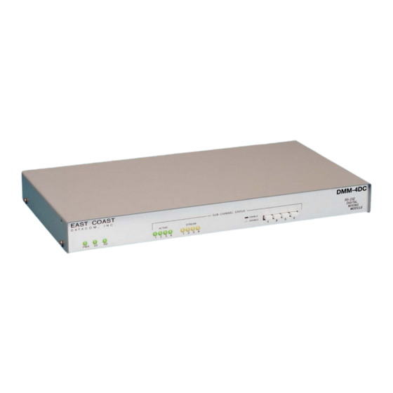
TABLE OF CONTENTS CHAPTER 1 - INTRODUCTION ......... Page 1 FUNCTIONAL DESCRIPTION . - Page 2 MODEL: DMM-4DC DESCRIPTION: DIGITAL MIXING MODULE -48VDC POWER SUPPLY January 22, 2002 FOR TECHNICAL SUPPORT CALL: East Coast Datacom, Inc. 245 Gus Hipp Blvd., STE 3 Rockledge, FL 32955 TEL: (800) 240-7948 or (321) 637-9922 FAX: (321) 637-9980 Web Site: http://www.ecdata.com...
- Page 3 Always observe standard safety precautions during installation, operation and maintenance of this product. To avoid the possibility of electrical shock, be sure to disconnect the DC power source from the DMM-4DC unit before you remove the cover or perform any repairs. PROPRIETARY NOTICE The information contained herein is proprietary to East Coast Datacom, Inc.
-
Page 4: Chapter 1 - Introduction
/ DSU or computer port. Any combination of terminals and modems may be used in a network environment. Each port of the DMM-4DC may be selected as a DCE or DTE interface. Once installed, system and network efficiency are increased through higher host processor utilization coupled with the significant decrease in idle time between host / terminal traffic sessions. -
Page 5: Theory Of Operation
RTS (Request To Send for terminals) or DCD (Data Carrier Detect for modems). When RTS or DCD is raised, the DMM-4DC will lock on to that port and allow that device to communicate to the Host Site. The DMM-4DC will remain locked onto that port until RTS or DCD is dropped. -
Page 6: Rs-232 Electrical Interface
DMM-4DC OPERATIONS MANUAL RS-232 ELECTRICAL INTERFACE The DMM-4DC user data ports are EIA RS-232 compliant, utilizing female DB-25 connectors. Refer to the interface chart in the Appendix for detailed interface information. The maximum data rate is 128kbps. The unit incorporates surge protection on each RS-232 data port. -
Page 7: Manual Dte/Dce Removal
To correct this condition, simply push the associated push-button switch for the subchannel that is streaming. All other DTE's will now continue to be serviced by the DMM-4DC. However, you still need to fix the offending DTE or DCE device that has RTS or DCD continually raised. -
Page 8: Enable Control (Ports 1 - 4)
RTS or DCD control signals. This option will monitor Transmit Data (TXD). When data is present, the DMM-4DC will lock onto the attached subchannel device. To Enable Control, move the jumper so that both headers are connected on positions 1 and 2. -
Page 9: Chapter 3 - Installation
VORSICHT: Befor Deckung Abnehmen Mach Strom Zu INPUT VOLTAGE The DMM-4DC is designed to accept DC voltages of 36 to 72 vdc, with 48 vdc as the nominal input voltage. Located on the back of the DMM-4DC is a 2-position terminal block. The block is removable and accepts a small slotted screwdriver to fasten the users DC voltage wires. -
Page 10: Default Configuration Switch Settings
If your system application requires one or more of the default settings to be changed, it will be necessary to remove the top cover of the DMM-4DC. Remove the DC Power source or Disconnect the DC Power before servicing the unit. Removal of the top cover is accomplished by using a small Philips screwdriver and removing the outside screws. -
Page 11: 4.0 - Appendix
DMM-4DC OPERATIONS MANUAL 4.0 - APPENDIX EIA INTERFACE CHART EIA RS-232-D INTERFACE CHART (DB-25 CONNECTOR) Pin No. CCITT Circuit Signal Description To DTE To DCE Circuit No. Name Shield Send Data Receive Data Request To Send Clear To Send DCE Ready... -
Page 12: Factory Default Chart
DMM-4DC OPERATIONS MANUAL FACTORY DEFAULT CHART 1 2 3 4 5 6 7 8 9 10 DMM-4DC FACTORY DEFAULT / SWITCH GUIDE Page 9... -
Page 13: Clocking / Application Diagram
DMM-4DC OPERATIONS MANUAL CLOCKING / APPLICATION DIAGRAM MODEM TERMINAL HOST MODEM CONNECTED TO CONNECTED TO (SLAVE) DMM-4, PORT 1 DMM-4 DMM-4, MASTER PORT 4 RTS DCD 8 CONTROL 5 CTS RX DATA 3 BUFFER 3 RX DATA RX CLOCK 17... -
Page 14: 4.4 User Notes
DMM-4DC OPERATIONS MANUAL 4.4 USER NOTES: Page 11... -
Page 15: 4.5 Technical Specifications
DMM-4DC OPERATIONS MANUAL 4.5 TECHNICAL SPECIFICATIONS Application Front Panel Multiple Sync/Async DCE/DTE devices operating Indicators: Power, Transmit Data, Receive Data, in a polled or contention environment, to share one Channel Active, Channel Stream DCE/DTE port Switches: Enable/Disable of each Sub-channel...
Need help?
Do you have a question about the DMM-4DC and is the answer not in the manual?
Questions and answers