
Summary of Contents for Solid Alliance N2ROU
- Page 1 Alliance_N2ROU (Remote Unit) User Manual SOLiD, Inc. 10,9th Floor, SOLiD Space220 Pangyoyeok-ro, Bundang-gu, Seongnam-si, Gyeonggi-do, Korea 393-400 Tel: +82-31-627-6290 Fax: +82-31-627-6209 Confidential & Proprietary 1/28...
- Page 2 BICSI (Building Industry Consulting Service International). Copyright This manual is written and produced by SOLiD and printed in the USA. All rights are reserved © 2015 SOLiD. Confidential and proprietary. Information contained in this document is company private to SOLiD and should not be modified, used, copied, reproduced or disclosed in whole or in part without the written consent of SOLiD.
-
Page 3: Table Of Contents
Contents Section1 1.1 Safety & Certification Notice ................4 Section2 2.1 Overview ......................7 2.2 N2ROU ......................8 Section3 3.1 Functional Description ..................3.2 N2ROU Component ..................9 3.3 Dimension ..................... 11 Section4 4.1 Installation ....................12 4.3 Install N2ROU ....................12 4.3.1 Install N2ROU .................... -
Page 4: Safety & Certification Notice
Section1 1.1 Safety & Certification Notice “Only qualified personnel should handle the DAS equipment. Any person involved in installation or service of the DAS should understand and follow these safety guidelines.” - Obey all general and regional safety regulations relating to work on high voltage installations, as well as regulations covering correct use of tools and personal protective equipment. - Page 5 FCC: This equipment complies with the applicable sections of Title 47 CFR Parts 15,22,24, 27 and 90 UL/CUL: This equipment complies with UL and CUL 1950-1 Standard for safety for information technology equipment,including electrical business equipment FDA/CDRH: This equipment uses a Class 1 LASER according to FDA/CDRH Rules.This product conforms to all applicable standards of 21 CFR Chapter 1, Subchaper J, Part 1040 - A readyily accessible disconnect device shall be incorporated external to the equipment.
- Page 6 - Access can only be gained by SERVICE PERSONS or by USERS who have been instructed about the reasons for the restrictions applied to the location and about any precautions that shall be taken; and - Access is through the use of a TOOL or lock and key, or other means of security, and is on trolled by the authority responsible for the location.
-
Page 7: Section2
Section2 2.1 Overview The N2ROU is a coverage system for in-building services delivering voice and data in high quality and for seamlessly. As a distributed antenna system, it provides analog and digital phone systems that are served in multiple bands through one antenna. The system covers general public institutions and private facilities. -
Page 8: N2Rou
The system is featured with the following: Flexibility & Scalability Support fiber-optic ports up to 60 Clustering multiple-buildings (campus) as one coverage Option structures Modular frequency upgrade Multi-Band, Multi Operator Signals with a plurality of service provider transmit simultaneously ... -
Page 9: Section3
Section3 N2ROU Component The following figure shows internal configuration of the N2ROU fully equipped with frequency bands. Figure 3.5 – Internal View of Remote Unit The N2ROU receives TX optical signals from Head-End and converts them into RF signals. The converted RF signals are amplified through High Power Amp in a corresponding RDU, combined with Multiplexer module and then radiated to the antenna port. - Page 10 The following table describes components of N2ROU. Unit Description Remote Drive Unit Amplify TX signals N2RDU Amplify RX signals Remove other signals through BPF Remote AC Power Supply Unit RPSU (AC) Input power: 90~280 VAC Output power: +29.2 VDC Remote DC Power Supply Unit RPSU (DC) Input power: -42 ~ -56 VDC Output power: +29.2 VDC...
-
Page 11: Dimension
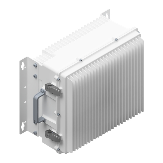
Allow to use a single antenna port for 7 bands Enclosure to satisfy IP66 ROU Enclosure Vertical Mount Wall Mount 3.1 Dimension Figure 3.6 – Remote Unit Dimension ITEM SPECIFICATION REMARK 18.5”x16.5" (10 RU) x 10.2” Dimensions (WxHxD) Including Bracket (470mm x 420mm x 260mm) Max. -
Page 12: Section4
Section4 4.1 Installation This chapter describes how to install each unit and optical cables. It also explains how to install shelves or enclosuers of each unit, power cabling method and optical cabling and RF interface. Required accessories and tools for installation are list up in the below table. 4.2 Install N2ROU 4.2.1 Install N2ROU The N2ROU uses a unibody enclosure that is NEMA 4 (IP66) certified to withstand water and... - Page 13 Figure 4.2 – N2ROU Wall Mount Dimensions Figure 4.3 – N2ROU Rack Mount Dimensions Confidential & Proprietary 13/28...
- Page 14 N2ROU Wall Mount Procedure The enclosure comes with the bracket for wall mounting. It doesn’t need to remove the bracket to install the enclosure, simply install and tighten 4 mounting bolts to secure the unit. First, install 2 of M12 mounting bolts roughly half way into the wall. Mount the enclosure and tighten the bolts.
- Page 15 N2ROU Components N2ROU has the following components: Unit Description Remark Enclosure N2ROU_BASE_AC or N2ROU_BASE_DC RCPU Remote Central Processor Unit R_OPTIC Remote Optic (only Remote Unit) RPSU Remote AC or DC Power Supply Unit Power Cable MS Connector with 4 holes N2RDU_781921 N2RDU_2300 ANT1...
-
Page 16: N2Rou Power Cabling
4.2.2 N2ROU Power Cabling AC Power The N2ROU supports only AC 120V input power and only a single type of power cable is provided. The pin discription of AC port is as below. Pay attention to the correct polarity. AC Power Port MS Connector No. - Page 17 DC Power The N2ROU supports only DC48V input power and a single type of power cable is provided. The pin discription of DC port is below. Pay attention to the correct polarity. DC Power Port MS Connector No. Name Description Not connected Not connected +48V...
-
Page 18: N2Rou Ground Cabling
4.2.3 N2ROU Ground Cabling The grounding terminal is located at the bottom of N2ROU enclosure fixed by an M6 screw. Compression terminal is attached already when it is delivered. The recommended thickness of cable is AWG#6 copper grounding wire. Figure 4.7 – Location of Ground Terminal The specification of compression terminal is as follows. - Page 19 The required part number is JOCO 0102-RS06 that supports AWG 6. To install the grounding cable, follow the steps below. Figure 4.9 –Installing Ground Terminal The procedures are 1. Loosen two M6 screws and then take compression terminal off 2. Insert AWG#6 grounding wire into terminal, and then compress a terminal using the tool 3.
-
Page 20: Optical Cabling
4.2.4 Optical Cabling The Optical connector is located at the bottom of the N2ROU. Optical cable can be connected by using its connectors. Figure 4.10 –Optical Connector Refer to the figure below for detailed information. The figure is based on LC type, but can be applied to SC type as well. -
Page 21: Installing Aor (Optional)
4.2.5 Installing AOR (Optional) The N2ROU can add Add on Remote (AOR) as optional remote unit. To install and connect the N2ROU with AOR, the materials listed blow are required. Accessory Description Specification Remark MS-3106A-14S- 5P(M) ST to Inner I/O Cable SMH200(F) ST_0.5m N(F) ST to SMBL(M) - Page 22 To connect AOR with the N2ROU, the steps listed blow must be done in advance. Confidential & Proprietary 22/28...
- Page 23 Figure 4.23 – Priliminary Work for Installing AOR The procedures are 1. Remove the dummy cover from the port that is used for connecting AOR. 2. The location of ports that need to be removed can be found in the figure No. 2 (The ports are circled in red.).
- Page 24 The following figure shows the diagrm connecting N2ROU with AOR. Refer to the figure below for cabling after the preliminary work. For legacy BIUand eBIU do not need this preliminary work, but for the new version, the preliminary work is required in order to connect AOR. For connecting AOR with the N2ROU, pay attention to the cable length.
-
Page 25: Section5
Section5 5.1 Specifications Mechanical Specification Mounting Type Wall or rack mounting Antenna port type: 4.3-10 DIN (M) type Connectors Fiber connectors: SC/APC for connecting to iODU or OEU Serial interface RS-232 9-pin D-sub Male for connecting management PC Craft Port (on CPU) In/Output Port Type N Female for connecting AOR... -
Page 26: Rf Performance
Optics SC/APC (Step Ferrule) Laser Diode/Photo Diode 1550nm/1310nm (Coaxial Type) Optical Loss Max 5dBo (4-port optical module); Max 10dBo (1-port optical module) 5.2 RF Performance N2RDU Specifications per Band Frequency range Bandwidth Output Power Unit Name (TX/RX) (TX/RX) TX(MHz) RX(MHz) 699~716 (B1) 39 / 17, 21 +33 / -5... - Page 27 FCC/IC User Warning FCC PART 15.105 STATEMENT This equipment has been tested and found to comply with the limits for a Class A digital device, pursuant to part 15 of the FCC Rules. These limits are designed to provide reasonable protection against harmful interference when the equipment is operated in a commercial environment.
- Page 28 RSS-GEN, SEC. 7.1.2 – (DETACHABLE ANTENNAS) This radio transmitter (identify the device by certification number, or model number if Category II)has been approved by Industry Canada to operate with the antenna types listed below with the maximum permissible gain and required antenna impedance for each antenna type indicated.
Need help?
Do you have a question about the Alliance N2ROU and is the answer not in the manual?
Questions and answers