
Related Manuals for SMC Networks ZQ A Series

Summary of Contents for SMC Networks ZQ A Series
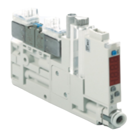
- Page 1 Doc. No. ZQ-OM01301-A Product name Space Saving Vacuum Ejector Unit Model/ Series/ Product Number ZQ□A Series...
-
Page 2: Table Of Contents
Doc. No. ZQ-OM01301-A Contents Safety Instructions 1. How to Order 2. Summary of Product Parts 3. Mounting and Installation 3.1. Installation 3.2. Operating Environment 3.3. Air Supply 3.4. Piping 3.5. Wiring 4. Solenoid Valve 5. Vacuum Pressure Switch 6. Vacuum release flow adjusting needle 7. -
Page 3: Safety Instructions
Doc. No. ZQ-OM01301-A pace Saving Vacuum Ejector Unit/ZQ□A Series Safety Instructions These safety instructions are intended to prevent hazardous situations and/or equipment damage. These instructions indicate the level of potential hazard with the labels of "Caution", "Warning" or "Danger". They are all important notes for safety and must be followed in addition to International Standards (ISO/IEC) and other safety regulations. - Page 4 Doc. No. ZQ-OM01301-A pace Saving Vacuum Ejector Unit/ZQ□A Series Safety Instructions Caution The product is provided for use in manufacturing industries. The product herein described is basically provided for peaceful use in manufacturing industries. If considering using the product in other industries, consult SMC beforehand and exchange specifications or a contract if necessary.
- Page 5 Doc. No. ZQ-OM01301-A ■Safety Instructions Warning ■Do not disassemble, modify (including the replacement of board) or repair other than instructed in this manual. Otherwise, an injury or failure can result. Disassembly prohibited ■Do not operate the product outside of the specifications. Do not use the product with flammable or harmful fluids.
-
Page 6: How To Order
Doc. No. ZQ-OM01301-A 1.How to Order Vacuum Ejector System (without energy saving function) Model of a single unit ZQ 05 1U A-K15L B-EA M G -3 3-N (1) (2) (4)(5) (6) (7) (8)(9)(10)(11)(12) (7) Vacuum pressure switch unit specifications Note 3) With unit selection function (1) Nozzle nominal size Fixed SI unit (kPa) - Page 7 Doc. No. ZQ-OM01301-A Vacuum Ejector System (with energy saving function) Model of a single unit ZQ 05 1U A-K15LO B-VA M W-3 3-N (1) (2) (4) (5) (6) (7)(8)(9) (6) Lead wire specifications (1) Nozzle nominal size No lead wire with connector Lead wire for energy saving switch (2 m, included in the package) (7) Fitting (V port)
- Page 8 Doc. No. ZQ-OM01301-A Vacuum pump system Model of a single unit ZQ000 U A-K15L B-EA M G-3 3-N (3)(4) (5) (6) (7) (8)(9)(10) (1) Body type (6) Vacuum pressure switch unit specifications For single unit Note 4) With unit selection function For manifold Fixed SI unit (kPa) Note 4)
- Page 9 Doc. No. ZQ-OM01301-A Vacuum Pump System Manifold ZZQ108A-S O C-A (3) (4) (3) Vacuum release pressure supply port (PD port) (1) Number of stations None (Release pressure is 1 stations supplied from the P port.) 2 stations Note 2) Provided (Breaking pressure: Supplied :...
-
Page 10: Summary Of Product Parts
Doc. No. ZQ-OM01301-A 2. Summary of Product Parts 2.1 Summary of Product Parts Standalone product (Vacuum ejector system) Pilot pressure exhaust (PE) port Release pilot valve Vacuum break flow adjusting needle Supply pilot valve Suction filter Mounting hole (2 parts) Exhaust port Vacuum (Both sides) - Page 11 Doc. No. ZQ-OM01301-A Manifold product (Vacuum ejector) Pilot pressure exhaust (PE) port (2 parts) Exhaust part Mounting Vacuum hole pressure supply (PV) port (4 parts) (2 parts) Manifold product (Vacuum pump system) Vacuum pressure supply (PV) port Pilot pressure supply (PS) port (One port for each;...
-
Page 12: Mounting And Installation
Doc. No. ZQ-OM01301-A 3. Mounting and Installation 3.1 Mounting 3.1.1 Standalone product (Direct mounting) 1) Directly mount the product on the wall surface, etc. by using the mounting holes (2 x 3.2) ø in the body. 2) Use the recommended tightening torque (0.54 to 0.66 Nm) to mount the product. Mounting hole (2 parts) 3.1.2 Standalone product (Mounting with a bracket) -
Page 13: Operating Environment
Doc. No. ZQ-OM01301-A 3.1.4 Precautions 1) When installing the product, allow sufficient space for maintenance and inspection. 2) Tightening torques exceeding the recommended values may damage the product and mounting screws. Insufficient torque can cause displacement of the body from its proper position as well as looseness of the mounting screws. -
Page 14: Air Supply
Doc. No. ZQ-OM01301-A 3.3 Air supply 3.3.1 Air quality 1) Using compressed air which contains chemicals, synthetic oils containing organic solvents, salts or corrosive gases, etc. can cause damage or malfunction. Do not use with fluid or in an environment which contains harmful impurities. 2) If the compressed air contains excessive drainage or carbon powder, it can stick to the vacuum generating part (the nozzle diffuser) or inside of the solenoid valve or the pressure switch for vacuum and cause deterioration of the performance or operation failure. -
Page 15: Piping
Doc. No. ZQ-OM01301-A 3.4 Piping 3.4.1 Port size The port sizes and operating pressure ranges are listed below. For the manifold type, ports are used in common for the end plate. When supplying from one side, plug the port not in use. Single unit type Port size Operating pressure... - Page 16 Doc. No. ZQ-OM01301-A 3.4.2 Piping to ports 1) When piping fittings, etc. are connected to the pilot pressure exhaust (PE) port (M3) for the single unit type, secure the part provided with the port, tighten it by hand, then additionally tighten by approximately one fourth of a turn using an appropriate tool. (Recommended tightening torque: 0.4 to 0.5 Nm) 2) When piping fittings, etc.
-
Page 17: Wiring
Doc. No. ZQ-OM01301-A 3.4.4 Precautions for air tubes 1) Route tubes to prevent twisting, tension, moment loads, vibration or impact from being applied to the tubes. Failing to route correctly can cause damage to the fittings and will crush or burst tubing, or it may come out. 2) Piping to the product is assumed to be static piping. -
Page 18: Solenoid Valve
Doc. No. ZQ-OM01301-A 4. Solenoid valve 4.1 Manual override There are 2 types of manual override operation. Push the manual override with a screwdriver until it reaches the end. Confirm that the product operates safely before the operation of the manual override. Manual override operation type Nil: Non-locking push type B: Slotted locking type... -
Page 19: Vacuum Pressure Switch
Doc. No. ZQ-OM01301-A 5. Vacuum pressure switch 5.1 Internal Circuit and Wiring Examples 5.2.1 Vacuum pressure switch NPN (2 output) PNP (2 output) Brown DC(+) Brown DC(+) 茶 DC (+) 茶 DC (+) Lord Black OUT1 Black OUT1 Black OUT1 Black OUT1 Lord Lord... -
Page 20: Vacuum Release Flow Adjusting Needle
Doc. No. ZQ-OM01301-A 6. Vacuum release flow adjusting needle 6.1 Vacuum release flow adjusting method Vacuum release air is output by turning the release valve ON. The flow rate of vacuum release air can be adjusted by altering the vacuum release flow adjustment needle. Loosen the lock nut and adjust the vacuum release flow adjusting needle located at the end of the lock nut using a flat blade screwdriver, etc. -
Page 21: Structural Drawing And Replacement Of Parts
Doc. No. ZQ-OM01301-A 7. Structural Drawing and Replacement of Part 7.1 Construction (single unit) Vacuum ejector Specifications Vacuum pump system specification Component Parts Description Material Note Brass and aluminum alloy are used in Body addition to resin supply valve, release valve POM, Aluminum alloy assembly Nozzle... - Page 22 Doc. No. ZQ-OM01301-A 7.2 Manifold exploded view Single unit for manifold b) view a) part a) part a) part Procedure for increasing and decreasing the number of manifold stations Disassembly (1) Remove the clamping rods (2 pcs.). (2) Remove end block L (Be careful not to drop the gasket). Assembly 1.
- Page 23 Doc. No. ZQ-OM01301-A 7.3 How to Order Replacement Parts Pilot valve for supply/ release Pilot valve for N.C. supply/ release Z1-V114-5LUB-A (1) (2) (1) Electrical entry L-type plug connector, with 0.3 m lead wire L-type plug connector, without connector (2) Manual Non-locking push type Slotted locking type N.O.
- Page 24 Doc. No. ZQ-OM01301-A Vacuum pressure switch (with suction filter) ZQ-ZSEA M G K-2-A (1) (2)(3)(4)(5) (1) Vacuum pressure switch specifications Symbol Pressure range Output specifications [kPa] NPN2 output PNP2 output 0 to -100 NPN1 output + analog voltage PNP1 output + analog voltage NPN2 output PNP2 output NPN1 output + analog voltage...
- Page 25 Doc. No. ZQ-OM01301-A Lead wire with connector for vacuum pressure switch Lead wire with connector for vacuum pressure switch ZS-39-5G Lead wire with connector for energy saving Pressure switch ZQ1-LW6-N-A (1) Output NPN open collector PNP open collector Silencer plate assembly ZQ1-PL11-A Filter vessel assembly ZQ1-FC1-A...
- Page 26 Doc. No. ZQ-OM01301-A Clamping rod assembly (2 pcs. are included in one set) ZQ1-SR1-04-A (1) Number of stations 1 stations 2 stations : : 8 stations Sound absorbing material (for manifold ) (2 pcs. are included in one set) ZQ1-SE2-A Silencer block assembly (2 pcs.
-
Page 27: Maintenance
Doc. No. ZQ-OM01301-A 8. Maintenance Perform the following checks and maintenance in order to use the vacuum unit safely and in an appropriate way. 8.1 How to replace the Silencer Single unit type 1) Loosen the mounting screws (2 pcs) of the silencer plates to remove the silencer plates (2 pcs.) and the sound absorbing material. - Page 28 Doc. No. ZQ-OM01301-A 8.2 How to replace the filter element 1) Loosen the tension bolt and remove the filter case. 2) Replace the filter element in the filter case. 3) Assemble the filter case with the tension bolt. (Recommended tightening torque: 0.12 to 0.18 Nm) tension bolt filter vessel filter element...
- Page 29 Doc. No. ZQ-OM01301-A 8.4 How to replace the vacuum pressure switch 1) Remove the V port fitting fixing clip, loosen the mounting screws (2pcs.) of the vacuum pressure switch, and then remove the vacuum pressure switch. 2) Replace the vacuum pressure switch and assemble it by using the mounting screws (2pcs.). (Recommended tightening torque: 0.11 to 0.13Nm)...
- Page 30 Doc. No. ZQ-OM01301-A 8.6 Actuators/Precautions 1) Maintenance should be performed according to the procedure indicated in the Operation Manual. Incorrect handling can cause damage of equipment and device, and operation failure. 2) During maintenance, compressed air can be dangerous when handled incorrectly. The assembly, handling, repair and element replacement of pneumatic systems should be performed by a knowledgeable and experienced person.
-
Page 31: Specifications
Doc. No. ZQ-OM01301-A 9. Specifications 9.1 Product specifications General Specifications Item ZQ□A series Operating temperature range [ 5 to 50 (No condensation) Fluid Vibration resistance [m/s Note1) Note 2) Impact resistance [m/s Standards CE marking, RoHS Note 1) 10 to 150 Hz., 2 hours in the directions of X, Y, and Z respectively (not energized, initial value) Note 2) 3 times in the directions of X, Y, and Z respectively (not energized, initial value) Vacuum ejector system specifications Item... - Page 32 Doc. No. ZQ-OM01301-A 9.2 Weight Single part number Model, additional specifications Weight [g] □ ZQ□ UA-K15L-F-00-N (Basic type for single unit) □ ZQ□ MA-K15L-F-0 (Basic type for manifold) Without release valve Supply valve N.O. specification With vacuum pressure switch (Lead wire is not included) Bracket assembly type Lead wire with connector for vacuum pressure switch Lead wire with connector for energy saving vacuum switch...
- Page 33 Doc. No. ZQ-OM01301-A Vacuum Switch Specification ZSE10 Pressure switch Pressure switch for Product Number Vacuum for compound vacuum with pressure switch pressure energy saving function Rated pressure range [kP] 0 to -101 -100 to 100 Set / display pressure range [kPa] 10 to -101 -105 to 105 Proof pressure [kPa]...
-
Page 34: Pneumatic Circuit
Doc. No. ZQ-OM01301-A 10. Pneumatic Circuit Vacuum ejector Single unit type ZQ□1UA-□5L□-□□□-□□ □ □□ □ □1UA- J1 5L- □ □□-□□ □1UA- K1 5L- □□-□□ □1UA- K1 5L- □□-□□ Vacuum pump system Single unit type ZQ000UA-□5L□-□□□-□□ □□ □□ ZQ000UA- J1 5L- □□... - Page 35 Doc. No. ZQ-OM01301-A Vacuum ejector Manifold type (with the PD-port) ZZQ1□A-BSC *ZQ□3MA-K15L-□□□-□-S *ZQ□3MA-K25L-□□□K-□-S □ □ □3MA- K1 5L- □□-□- □3MA- K2 5L- □□K-□-S Vacuum pump system Manifold type (without the PD-port) ZZQ1□A-ROB *ZQ000MA-K15L-□□□-□ *ZQ000MA-K25L-□□□-□ *ZQ000MA-J15L-F-□ *ZQ000MA- J1 5L- F -□ *ZQ000MA- K1 5L- □□-□...
-
Page 36: Exhaust Characteristics, Flow Characteristics, Vacuum Pump Flow Characteristics, And Vacuum Release Flow Rate Characteristics
Doc. No. ZQ-OM01301-A 11. Exhaust Characteristics, Flow Characteristics, Vacuum Pump Flow Characteristics, and Vacuum Release Flow Rate Characteristics 11.1 Vacuum ejector exhaust characteristics / Flow characteristics (representative values) ZQ05□A Flow Rate Characteristics Supply pressure:0.35MPa Exhaust Characteristics -100 Vacuum pressure Air consumption Suction flow rate Supply pressure[MPa] Suction flow rate [L/min (AMR) ]... - Page 37 Doc. No. ZQ-OM01301-A 11.2 Flow characteristics of the vacuum pump system (representative values) ZQ000A -100 The flow rate at the final adsorbing part can vary depending on the piping conditions to the vacuum port. (This graph shows values when the V port with ø 6 is used.) Suction flow [L/min (AMR) ] 11.3 Break Flow Rate Characteristics (representative value)
-
Page 38: Handling Precautions
Doc. No. ZQ-OM01301-A Maximum vacuum release flow rate Vacuum release flow rates in product specifications and according to the V port size [L/min (ANR) ] V Port Supply pressure error □ □ □ □ ZQ05 ZQ07 ZQ10 ZQ000 Size [MPa] Common Individual Common... -
Page 39: Troubleshooting
Doc. No. ZQ-OM01301-A 13. Troubleshooting If the product fails in any way, perform the following troubleshooting measures. Failure phenomenon Possible causes Countermeasures Vacuum is not generated Clogging by foreign matter or particles See (1) and (2) Decline in the See (3) and (4) power supply voltage Electrical wire... - Page 40 Doc. No. ZQ-OM01301-A Countermeasures ■ Countermeasures Oil mist in the supply air or particles in the piping cause clogging if they enter the ejector. This may cause operation failure. Blow the air piping with air to eliminate particles. Installing the mist separator and air filter for cleaner supply air is recommended.
- Page 41 Doc. No. ZQ-OM01301-A Countermeasures When the ejector adsorbs the workpiece by generating a vacuum, high speed air coming out of the nozzle collides into the diffuser I.D. and bounces back, generating vibration in the exhaust air. Because of this, the vacuum pressure fluctuates slightly and is not stabilized. The workpiece can be adsorbed when the ejector is used in this condition.
- Page 42 Doc. No. ZQ-OM01301-A Revision history A’ P.22 Change of the spare part numbers for the solenoid valve P.24 Change of the spare part numbers for the V port fitting P.25 Change of the spare part numbers for the Washer assembly P.27 P.28 Added items to 8.
Need help?
Do you have a question about the ZQ A Series and is the answer not in the manual?
Questions and answers