Table of Contents
Troubleshooting

Related Manuals for Parker Balston NitroFlow60


Summary of Contents for Parker Balston NitroFlow60
- Page 1 Installation, Operation and Maintenance Manual Bulletin TI-NITROFLOW60-G NitroFlow60 and NitroFlow60D Generators NitroFlow60 and NitroFlow60D Installation, Operation, and Maintenance Manual 1-800-343-4048 www.labgasgenerators.com...
-
Page 2: Explanation Of Warning Symbols
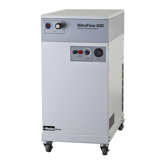
Installation, Operation and Maintenance Manual Bulletin TI-NITROFLOW60-G NitroFlow60 and NitroFlow60D Generators Explanation of Warning Symbols Symbol Description Caution, refer to accompanying documents for explanation. Refer to the caution note indicated for explanation. Caution, risk of electric shock. Refer to the warning note indicated for explanation. - Page 3 Please refer to page 2 for an explanation of the caution/warning safety certification of this product. Retain these instructions for symbols used throughout this manual. future reference. Figure 1 Model NitroFlow60 & NitroFlow60D Nitrogen Generator 1-800-343-4048 www.labgasgenerators.com...
- Page 4 Bulletin TI-NITROFLOW60-G NitroFlow60 and NitroFlow60D Generators General Description The NitroFlow60 Nitrogen Generator System Series are available in two models (Figure 1): NitroFlow60 Nitrogen Generator System(No Dry Air output) NitroFlow60D Nitrogen Generator System(Dry Air output) The integrated system is engineered to produce pure nitrogen gas and clean, dry -40°F dew point air gas from compressed air delivered by a carefully matched scroll compressor.
-
Page 5: Installation
NitroFlow60 and NitroFlow60D Generators Water Separator The NitroFlow60 generator series incorporates a water separator to remove liquid water from the compressed air before it reaches the prefilters.The liquids are collected in the supplied disposal container. Refer to the included installation and service instructions, 2F101H, for maintenance instructions. - Page 6 208VAC. See the accessory section on page 17. Main supply voltage fluctuations must be within ±10% of the nominal main supply voltage. For the JA and WD Models: The NitroFlow60 Generator Series, rated at 230V, 50 Hz, single phase, 13A fully loaded installation requires the following electrical setup: 1 The supply line should be dedicated to the generator.
- Page 7 Receptacle for Model: NA (North America) Piping There are six plastic tubing connections for the NitroFlow60 generator: (1) nitrogen outlet gas connection; (1) dry air outlet gas connection (NitroFlow60D only); (4) drain connections. Press the tubing into the quick-connect fittings. Assure tubing is fully inserted (about ½”). Tubing is provided in the installation kit.
-
Page 8: Operation
Installation, Operation and Maintenance Manual Bulletin TI-NITROFLOW60-G NitroFlow60 and NitroFlow60D Generators Figure 9 Figure 10 Recommended A03-0286 voltage step-down transformer - If your facility supply voltage is 255V or higher, then the use of this transformer is required. Accessories A03-0281 voltage step-up transformer - If your facility supply voltage is 195V or lower, then the use of this transformer is required. - Page 9 Maintenance Maintenance tasks for the NitroFlow60 and NitroFlow60D Generator should be performed by trained personnel familiar with the service and safety precautions of electromechanical devices to avoid injury or damage. Safety risks that may affect the service personnel are identified with the necessary protective measures described.
- Page 10 (P/N 100-09-BX) 8700 hours Carbon Module (P/N B04-0525) 8700 hours ¹ Frequency hours for NitroFlow60 and NitroFlow60D are recorded by an hour meter. Note: The meter indicates 00000.0 hours. The hour meter does not reset. Figure 17, Maintenance Items 1-800-343-4048 www.labgasgenerators.com...
- Page 11 Installation, Operation and Maintenance Manual Bulletin TI-NITROFLOW60-G NitroFlow60 and NitroFlow60D Generators Cleaning If necessary, wipe the generator with a clean, dry cloth on an as-needed basis. Do not use water, aerosols or other cleaning agents on the unit. Use of any liquid detergent to clean the unit could pose an electrical hazard.
- Page 12 Installation, Operation and Maintenance Manual Bulletin TI-NITROFLOW60-G NitroFlow60 and NitroFlow60D Generators Figure 21, belt diagram Grease Orbital 1 Remove the plastic dust cap from the pump (see figure 22). Scroll Compressor 2 Rotate the compressor pulley until the grease fitting is visible in the dust cap hole.
- Page 13 Installation, Operation and Maintenance Manual Bulletin TI-NITROFLOW60-G NitroFlow60 and NitroFlow60D Generators Grease Pin Crank Remove the side service panel (see figure 15). Bearing Remove the fan duct. Remove the nuts, bolts, and then the fixed scroll. Grease three pin crank bearings according to Table 1 and figure 23.
- Page 14 Schedule 2 These instructions describe the replacing of the two coalescing pre-filters, the two carbon modules, and two particulate filters in the NitroFlow60 Generator System Series. Instructions Generator must be set to “OFF” and pressure gage must read zero before filter replacement.
- Page 15 Figure 28 Figure 29 1 Remove the top panel from the NitroFlow60 Generator Series by removing two screws with a phillips head screwdriver and pulling top panel to the rear. 2 Disconnect the plastic tubing from the press fittings on the inlet and outlet ports of the module.
-
Page 16: System Specifications
632 lbs (287 kgs) ¹ Main supply voltage fluctiations not to exceed ± 10% of nominal voltage. Motor change installed in compressor Serial Number (H)8/8/2012-5284488-610 and after; NITROFLOW60 Serial Number, N260-0019 and after. Cautions The generator should be installed in an area with adequate ventilation to reduce the flammability of the oxygen-rich permeate stream. -
Page 17: Replacement Parts
If the compressor air supply is confirmed, remove lower side panel and relieve tank pressure using auto tank drain test button. Proceed to the NItroFlow60 generator Troubleshooting section (page 20), and begin troubleshooting the NitroFlow60 generator. -
Page 18: Compressor Troubleshooting
Installation, Operation and Maintenance Manual Bulletin TI-NITROFLOW60-G NitroFlow60 and NitroFlow60D Generators Compressor Troubleshooting Symptom Probable Cause Corrective Action • Power not plugged in • Plug in power cord POWER ON light (green) does not appear supply outlet • Power switch is not ON •... - Page 19 Installation, Operation and Maintenance Manual Bulletin TI-NITROFLOW60-G NitroFlow60 and NitroFlow60D Generators Compressor Troubleshooting Symptom Probable Cause Corrective Action TEMPERATURE HIGH light • Room temp is above 90°F • Add ventilation or air is on, Compressor shuts conditioning to room down •...
- Page 20 Installation, Operation and Maintenance Manual Bulletin TI-NITROFLOW60-G NitroFlow60 and NitroFlow60D Generators NitroFlow60 and NitroFlow60D Generator Troubleshooting Symptom Probable Cause Corrective Action • Compressor is not ON • Turn on compressor No pressure • Regulator is closed • Open pressure regulator •...
- Page 21 Installation, Operation and Maintenance Manual Bulletin TI-NITROFLOW60-G NitroFlow60 and NitroFlow60D Generators Don’t Forget To: Complete and mail or fax in your warranty registration card. Keep your product certification in a safe place. Call the Technical Services Department at 800-343-3038, 8AM to 5PM Eastern Time (North America only) or email at balstontechsupport@parker.com with any questions.
- Page 22 Installation, Operation and Maintenance Manual Bulletin TI-NITROFLOW60-G NitroFlow60 and NitroFlow60D Generators Figure 34 1-800-343-4048 www.labgasgenerators.com...
-
Page 23: Flow Rates
Installation, Operation and Maintenance Manual Bulletin TI-NITROFLOW60-G NitroFlow60 and NitroFlow60D Generators Flow Rates Nominal conditions for the charts are Temperature 68°F (20°C) and Ambient Pressure 14.7 psi [1013 mbar(a)]. The maximum pressure for the nitrogen is 101.5 psi. Flow meter accuracy +/-0.5 (99% purity). - Page 24 Installation, Operation and Maintenance Manual Bulletin TI-NITROFLOW60-G NitroFlow60 and NitroFlow60D Generators © 2012, 2015 Parker Hannifin Corporation Printed in U.S.A. Bulletin TI-NITROFLOW60-G 02/2015 Parker Hannifin Manufacturing Limited Parker Hannifin Corporation Filtration and Separation Division Division domnick hunter Filtration and Separation...
Need help?
Do you have a question about the NitroFlow60 and is the answer not in the manual?
Questions and answers