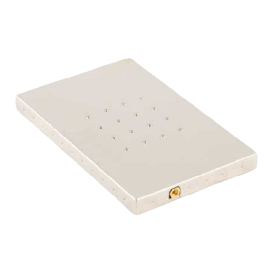
Summary of Contents for AWID SENTINEL-SENSE ADB-510
- Page 1 ADB-510 Page 1 7/16/2021 SENTINEL-SENSE ADB-510 & O - 041526 NSTALLATION PERATION ANUAL APPLIED WIRELESS ID...
-
Page 2: Fcc Compliance
COPYRIGHT ACKNOWLEDGEMENTS The contents of this document are the property of Applied Wireless Identifications Group, Inc. (AWID) and are copyrighted. All rights reserved. Any reproduction, in whole or in part, is strictly prohibited. For additional copies of this document please contact:... - Page 3 The antenna must be installed such that 23 cm can be maintained between the antenna and users. Manufacturer/ Antenna Antenna Model Max Gain (dBi) Impedance (Ω) Brand Type connector ANT-915CPS AWID Patch TNC, RP ANT-915-CP-R AWID Patch SMA, RP ANT-2012 AWID Patch SMA, RP ANT-915-CC-05...
- Page 4 ADB-510 Page 4 7/16/2021 2.8 Label and compliance information The final end product must be labeled in a visible area with the following: “Contains FCC ID: OGSADB510”. The grantee's FCC ID can be used only when all FCC compliance requirements are met. 2.9 Information on test modes and additional testing requirements This transmitter is tested in a standalone mobile RF exposure condition and any co-located or simultaneous transmission with other transmitter(s) or portable use...
-
Page 5: Industry Canada Compliance
ADB-510 Page 5 7/16/2021 INDUSTRY CANADA COMPLIANCE This device complies with ISED’s licence-exempt RSSs. Operation is subject to the following two conditions: (1) This device may not cause harmful interference, and (2) this device must accept any interference received, including interference that may cause undesired operation. - Page 6 Manufacturer/ Antenna Antenna Model Max Gain (dBi) Impedance (Ω) Brand Type connector ANT-915CPS AWID Patch TNC, RP ANT-915-CP-R AWID Patch SMA, RP ANT-2012 AWID Patch SMA, RP...
- Page 7 ADB-510 Page 7 7/16/2021 entre l'antenne et les utilisateurs. Le produit final doit être étiqueté dans un endroit visible avec l'inscription suivante: "Contient des IC: 6449A-ADB510". Manual Information to the End User The OEM integrator has to be aware not to provide information to the end user regarding how to install or remove this RF module in the user’s manual of the end product which integrates this module.
-
Page 8: Table Of Contents
NOTES ON SOFTWARE PROGRAMMING AND SYSTEM OPERATION ...... 15 4.3......................15 YSTEM PERATION 4.3.1. Running a Custom Software Application or the AWID Demo Program ....15 4.4........................15 SERS REFERENCE........................16 NOTE: READ AND USE THIS MANUAL FAILURE TO FOLLOW THE INSTALLATION (SET UP) GUIDE MAY RESULT IN POOR PERFORMANCE OR EVEN CAUSE PERMANENT DAMAGE TO THE READER, THUS VOIDS THE PRODUCT WARRANTY. -
Page 9: Revision History
ADB-510 Page 9 7/16/2021 REVISION HISTORY Version Revised By Date Sections Remarks Affected 6/2021 Initial version AWID Engineering 7/2021 AWID Engineering Editorial - IC Compliance statement 7/2021 p.2, p.5 AWID Engineering Updated – FCC, IC Compliance APPLIED WIRELESS ID... -
Page 10: Introduction
Thin passive tags with long-range performance 3.3 V (5.0V tolerable) Serial TTL logical interface Though ADB-510 can also be controlled from a non-Windows programming platform, AWID demo and FW upgrade programs are applications to run in Windows. APPLIED WIRELESS ID... -
Page 11: Specifications
ADB-510 Page 11 7/16/2021 2. SPECIFICATIONS Input voltage +5.8 VDC ~ 6 VDC (max) Input current 1.4 A max @ +6V Idle Power 0.5W in stand-by Protocol language ISO Type C, EPC Class 1 Gen 2 Read range Depends on type & size of labels used RF connectors MMCX (F) VSWR<1.2 @50OHMs Output power... -
Page 12: Connector Pin Assignment
ADB-510 Page 12 7/16/2021 2.2. CONNECTOR PIN ASSIGNMENT Function Function Reserved (**) Reserved Unit Enable (***) Reserved SCIR (***) +6.0 V SCIT +6.0 V (*) unit is disabled if pin 1 is low. (**) pin 7 is internally pulled high, user may leave this pin unconnected if manual control is not required. -
Page 13: Installation & Operation Guidelines
3.1. GENERAL WIRING REQUIREMENTS ADB-510 requires 10-pin flat flex cable (FFC) to connect from the supply source. Avoid using long (e.g., 10” or longer) cables when connecting the unit from the power supply source. AWID PROPRIETARY... -
Page 14: Installation Procedure
4. Installation Procedure This section provides installation and operation information for ADB-510 reader modules. 4.1. PARTS LIST Verify that all items listed below are present before starting the installation. o Sentinel-Sense ADB-510 Qty=1 o Documentation and Demo SW Qty=1 4.2. PREPARATION FOR INSTALLATION Familiarize yourself with the connectors and pin out assignment of each I/O connectors. -
Page 15: Notes On Software Programming And System Operation
4.3. SYSTEM OPERATION 4.3.1. Running a Custom Software Application or the AWID Demo Program If AWID Demo Program is not used, it is expected user will launch a Custom Software Application to send commands using AWID MPR Communication Protocol and/or the supporting SDK to the reader. -
Page 16: Reference
ADB-510 Page 16 7/16/2021 5. Reference MPR Communication Protocol – Doc# 041479 MPR Command Demo II Quick Reference Guide - Doc# 041483 AWID PROPRIETARY...


Need help?
Do you have a question about the SENTINEL-SENSE ADB-510 and is the answer not in the manual?
Questions and answers