Advertisement
Quick Links
The AC-160-C Wireless multifunctional relay
The AC-160-C wireless multifunctional relay (MFR) is a bi-directional
component of the JABLOTRON 100 system. The relay copies the status
of selected PG outputs when enrolled to the control panel. It can also
be installed as a stand-alone device and it reacts to activation from
up to 64 one–way detectors of the JA-15x series and JA-15xJ MS
and JA-16xJ keyfobs. MFR works according to the selected mode for
a particular detector/controller (Modes: extended copy, impulse, on/off,
change of status, always switches off and block the relay).
It has galvanically isolated relay contacts for switching power loads
of 230 V / 16 A. This product can only be installed by a trained
technician with a valid certificate issued by an authorised distributor.
The output relay can be controlled manually by a button (1)
on the front panel. In the stand-alone mode, the button serves to enrol
devices and configure their functions.
Installation
The
device
to mains electricity by a person who has
an adequate electrotechnical qualification.
It provides single pole switching and
doesn't provide safety isolation
The relay module is meant to be installed into standard plastic
electrical boxes. There must be a JA-11xR radio module enrolled
to the control panel to ensure cooperation with the system.
The MFR occupies one position in the JA-100 system.
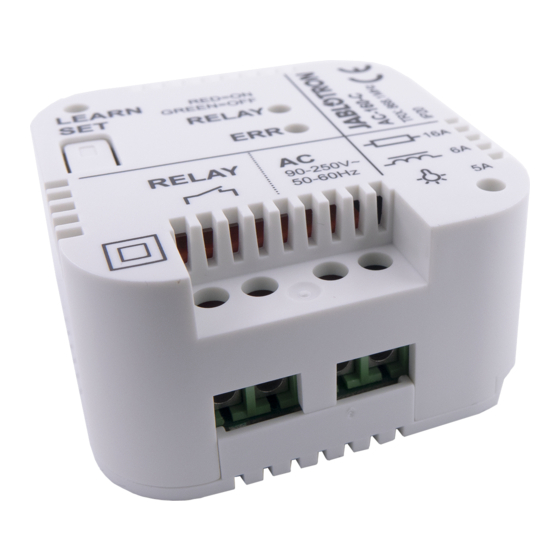
Figure: 1 – Learn (enroll)/set button; 2 – LED indicators;
3 – Relay output terminals; 4 – Mains power terminals 230 V AC
1.
Connect the power wires (230 V AC) to the terminals (4), and turn
the power on.
2.
Follow the control panel installation manual. Basic procedure:
a.
When the relay has been turned on, the 'RELAY' LED
switches to green and 'ERR' switches to yellow permanently
to indicate the relay has not been enrolled to the system yet
and also a detector has not been enrolled to the relay either.
b.
Using F-Link software, select the required position in the
Devices window and launch the enrollment mode by clicking
on the Enroll option.
c.
By pressing the Learn/Set (1) button longer than 3 s
(until the yellow LED starts flashing) the MFR sends
an
enrolling
signal
to the control panel is confirmed when the yellow LED turns
off.
3. Test the MFR function by pressing the button (1). After
approximately 0.5 s the output relay is activated. A switched relay is
indicated by a red LED (RELAY).
4. Connect the controlled device to the terminals of the MFR (3).
Notes:
The relay goes to standby mode, when the power is disconnected
or communication is lost with the control panel for more
than 1 minute. When the MFR has lost communication with
an enrolled device then the restoration interval is 20 minutes. Loss
of communication is indicated by permanent lighting of the 'ERR'
yellow LED).
When the mains or communication with a control panel is restored,
the MFR returns to the status given by pre-defined settings within
2 minutes (for wireless detectors with a periodical link test such
as the JA-151M, it can take up to 9 minutes).
The MFR doesn't maintain periodical communication with keyfobs
It is also possible to enroll the MFR to the system by entering the
production code
via
the
the production code is on the rear of the MFR. All digits
of the code are required (example: 1400-00-0000-0001)
JA-18x detectors are not compatible with the MFR
The AC-160-C wireless multipurpose relay
can
only
be
connected
.
to
the
control
panel.
Enrolling
F-Link
software.
A sticker
Multiple-input detectors such as the JA-150M are always
to be enrolled in one position and the relay is only triggered
by the first input of the detector.
After each pressing of the Learn/Set button the MFR changes
its status after 0.5 s, as well as when an enrollment signal 'LEARN'
is transmitted or while entering the relay's service mode – indicated
by the 'RELAY' LED. When a control panel is already enrolled,
the function can be disabled. See the settings below.
Setting the MFR properties
The module properties can be set in the Devices tab of the F-Link
software. Click on Internal settings option at the module's position
to open a dialogue window where you can set the following options:
Manual relay controlling: Enabled: a short press of the Learn/Set button
(1) changes the relay state (switches ON/OFF). Manual control is possible
even in a situation when the MFR doesn't communicate with the control
panel. Manual control can be completely disabled.
Reacts to PG(s): Enables activation of the MFR by one or more control
panel PG outputs.
Common timer: Determines the period of time during which
the output relay will be switched ON. The function differs according
to the pre-set mode of an enrolled device. This parameter serves
for setting the timing of the switching impulse of an impulse detector and
a keyfob. A status-mode type of detector with an "extended copy" reaction
makes the relay stay active for the whole time even when the detector goes
to standby. The timer can be set in pre-defined steps or your own time
in the F-Link software (from 1s up to 23h 59min 59s)
Enrolled devices: This window includes 64 positions to enroll
detectors or keyfobs. The first of two options to enroll them is to enter
the production code into the production code field. The second
is enrolling them via the Learn/Set button which is described
in the Enrolling the detectors and keyfobs chapter. In this case
it is recommended to use the internal menu only to check on or maintain
the modes of the enrolled detectors.
The MFR internal settings do not work
in online mode. That´s why it is not possible
to enroll devices via F-Link SW by sending
an enrollment signal. It is only possible
by entering the serial number and saving
the settings.
Mode: This option determines how the MFR will react to the activation
of an enrolled device.
None: the device has no function
Extended copy: This reaction is only for the detectors.
The MFR will be switched ON for as long as the detector
is activated. After the detector goes to standby mode, the MFR
extends activation with time set by the "common timer" function.
Switch On/Switch Off: This reaction is only for keyfobs
of the JA-15xJ and JA-16xJ series. The A(C) button switches
the MFR on and the B(D) button switches it off.
Impulse: detector activation or pressing a configured keyfob button
will
switch
ON
by the Common timer. The MFR can be kept switched on as long
as the configured keyfob button is pressed. Up to 60 seconds
maximum.
Change status: detector activation or pressing the configured
keyfob button changes the MFR's status
Always
switching
the configured keyfob button always switches off the MFR if there's
no active selected PG output in the control panel or a status
detector with extended copy mode.
Block: A particular active status-mode detector blocks switching
the MFR by other detectors for its whole activation period.
The A(C) button on an enrolled keyfob blocks the MFR on and the
B(D) button unblocks it. When blocking is over, the relay
is activated again as long as there is a request to switch on the
MFR by any status-mode detector or a PG output. Blocking
is indicated by the flashing green LED. Blocking during other
detector activation is indicated by alternate flashing in green/red
of the 'RELAY' LED.
Notes: The highest priority of the relay is blocking, next is triggering
a status detector or a PG output and then everything else
(timer, switch on/off, status change), so that a switched on relay can't be
switched off by, for example, a PG output.
Stand-alone mode
Up to 64 one-way communicating detectors of the JA-15x series
with
and keyfobs of the JA-15xJ MS and JA-16xJ series can be enrolled
to the MFR. Enrollment and setup of detector and keyfob mode is done
by the Learn/Set button (1). The relay can recognize 3 lengths
of pressing:
1 / 2
the
MFR
for
a
pre-defined
off:
detector
activation
time
given
or pressing
MLZ54603
Advertisement

Related Manuals for jablotron AC-160-C


Summary of Contents for jablotron AC-160-C
- Page 1 The AC-160-C wireless multifunctional relay (MFR) is a bi-directional to be enrolled in one position and the relay is only triggered component of the JABLOTRON 100 system. The relay copies the status by the first input of the detector. of selected PG outputs when enrolled to the control panel. It can also...
- Page 2 (ERC REC 70-03) Perform a long press of the Learn/Set button (1) until the yellow JABLOTRON ALARMS a.s. hereby declares that the AC-160-C LED starts flashing. Now release the button. The yellow LED is in a compliance with the relevant Union harmonisation indicates permanently and the red LED flashes.
Need help?
Do you have a question about the AC-160-C and is the answer not in the manual?
Questions and answers