Advertisement
Quick Links
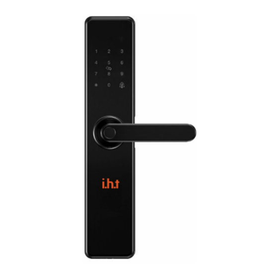
i.h.t Smart Lock Installation Instruction
Please read this instruction carefully before installation
Features
5-Way Access Methods
Battery Type / Life
Storage Capacity
Identity Time
Low Voltage Warning
Privacy Password
Fire Rating
IDL707
(WIFI)
Fingerprint, Password, Card, APP, Back-up Key
4×AA Battery / 1 Year
100 (Passwords, Fingerprints & Cards)
0.3 Seconds
≤4.6V
Random Numbers Can Be Added Before or After
120 Minutes (AU 1530.4:2014)
Installation
Safety Cautions
•
It is recommended to look for a professionals to install.
•
Please note that the connection power line can't be pressed or folded during installation.
•
Before the installation, the lock must be positioned according to the door opening
direction. The handle can't be adjusted after lock body is installed .
•
While installing, the door must be opened until the installation is completed. After the
installation is completed, test whether the front and back handle can unlock/lock using the
fingerprint, smart card, password (1234567890#) , APP and key.
•
If it does not work properly, please check if there is an improper installation, if the power
cord is loose or the batteries are inserted incorrectly.
•
Ensure no liquids are near the lock during installation.
Installation Overview
1. Confirm The Direction of The Door
This smart lock is suitable for Left Out/Left In/Right Out/Right In installation. 4 kinds of door
opening orientations.
1.
Front Panel
2.
Connection Column
3.
Square Steel
4.
Lock Body
5.
Connection power Line
6.
Back Panel
7.
Battery Cover
8.
Connection Column Screws
9.
Back Handle
10. Connection Column Screws
11. Latch-bolt
12. Dead-bolt
13. Lock Body Screws
14. Connection Column
15. Key Hole
16. Emergency Power Port
17. Front Handle
18. 'SET' Button
Advertisement

Summary of Contents for IHT Cordynamic IDL707
- Page 1 Square Steel Lock Body Connection power Line Back Panel Battery Cover Connection Column Screws Back Handle 10. Connection Column Screws IDL707 11. Latch-bolt 12. Dead-bolt (WIFI) 13. Lock Body Screws i.h.t Smart Lock Installation Instruction 14. Connection Column 15. Key Hole Please read this instruction carefully before installation 16.
- Page 2 2. Changing Handle Direction 6. Installing the Lock Front Handle Direction Change – Disassemble the direction Install two connection columns into the front panel changing screw and twist the hand downwards 180 degrees Installing the front panel: carefully and slowly. Once in position, screw the direction change Insert the suitable square steel into the lock body.
Need help?
Do you have a question about the IDL707 and is the answer not in the manual?
Questions and answers