Table of Contents
Advertisement
Quick Links
CONTENTS
Introduction .................................................................................................................................................................1
Comprehensive Annunciation Capabilities .............................................................................................................1
Rugged and Flexible Construction ..........................................................................................................................2
Simple Connections ................................................................................................................................................2
Style Number ..............................................................................................................................................................2
Specifications ..............................................................................................................................................................2
Control Power .........................................................................................................................................................2
Power Dissipation ...................................................................................................................................................2
Communication .......................................................................................................................................................2
Audible Alarm ..........................................................................................................................................................2
Temperature ............................................................................................................................................................2
Weight .....................................................................................................................................................................3
Type Test Data........................................................................................................................................................3
Agency Certification ................................................................................................................................................3
Functional Description ................................................................................................................................................3
Inputs ......................................................................................................................................................................3
Microprocessor........................................................................................................................................................4
Firmware .................................................................................................................................................................4
Controls and Indicators ...............................................................................................................................................4
Programmable Alarm and Pre-Alarm Indicator Configuration ....................................................................................5
Installation ...................................................................................................................................................................6
Mounting .................................................................................................................................................................6
Connections ............................................................................................................................................................9
Testing ..................................................................................................................................................................... 11
Test Equipment and Setup .................................................................................................................................. 11
Test Procedure..................................................................................................................................................... 11
INTRODUCTION
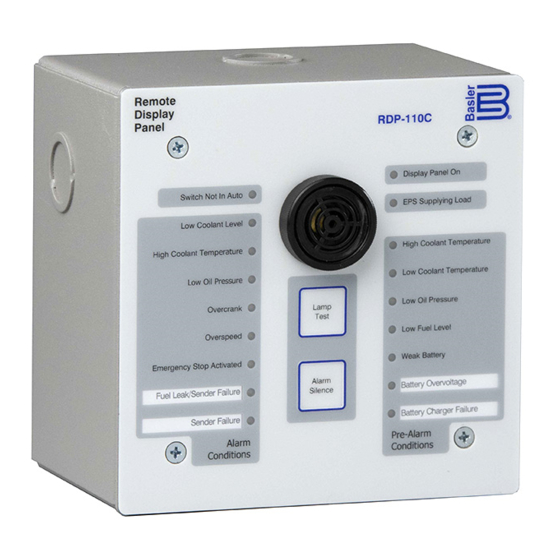
The RDP-110C Remote Display Panel provides remote annunciation of engine/generator status. When used with
Basler Digital Genset Controllers DGC-2020, DGC-2020ES, DGC-2020HD, DGC-500, or DGC-1000, the RDP-
110C provides compliance with NFPA 110 Level 1 and Level 2 requirements. The RDP-110C is suitable for use
with isolated generators or paralleled generating systems.
The RDP-110C serves as the successor to the RDP-110. The RDP-110C features identical functionality in a more
compact size, enabling its use in a broader range of applications. An optional adaptor plate enables convenient
replacement of an RDP-110 with an RDP-110C.
Comprehensive Annunciation Capabilities
The RDP-110C is equipped with the following LED indicators:
RDP-110C control power applied
•
Genset supplying load
•
DGC not operating in Auto mode
•
Six fixed-function alarms
•
Two programmable alarms
•
Publication
9318100995
For terms of service relating to this product and software, see the Commercial Terms of Products and Services document available at www.basler.com/terms.
www.basler.com
+1 618.654.2341 (USA)
info@basler.com
Instructions
Revision
-
Model
RDP-110C
Description
Remote Display Panel
Date
Sep 2020
Copyright
2020
Advertisement
Table of Contents

Summary of Contents for Basler RDP-110C
-
Page 1: Table Of Contents
Six fixed-function alarms • Two programmable alarms • Instructions Publication Revision Date Copyright 9318100995 — Sep 2020 2020 For terms of service relating to this product and software, see the Commercial Terms of Products and Services document available at www.basler.com/terms. -
Page 2: Rugged And Flexible Construction
STYLE NUMBER A style number defines the RDP-110C mounting configuration and Digital Genset Controller compatibility. The style number appears on a label located on the right side of the case. Figure 1 illustrates the RDP-110C style chart. Figure 1. RDP-110C Style Chart... -
Page 3: Weight
Agency Certification UL recognized per Standard 508. FUNCTIONAL DESCRIPTION The RDP-110C uses microprocessor-based technology to provide remote annunciation of engine and generator parameters. RDP-110C function blocks are illustrated in Figure 2 and described in the following paragraphs. Power RS-485 Lamp... -
Page 4: Microprocessor
Embedded firmware controls power-up initialization, annunciation element setup, and serial communication. When control power is applied to the RDP-110C, the firmware initiates a power-up sequence, checks the onboard memory, activates all annunciation functions, and begins monitoring for inputs from the DGC. -
Page 5: Programmable Alarm And Pre-Alarm Indicator Configuration
Battery charger failure. • When the RDP-110C is used with a DGC-2020, the bottom two LEDs (Battery Overvoltage and Battery Charger Failure) can be reprogrammed to indicate other pre-alarm conditions. See Programmable Alarm and Pre-Alarm Configuration for information about configuring the two programmable pre-alarm indicators. -
Page 6: Installation
“pass-through” or junction box for other site wiring. Two available mounting configurations provide the option of semi-flush mounting or surface (projection) mounting. If the RDP-110C will not be installed immediately, store it in the original shipping package in a moisture- and dust- free environment. - Page 7 Figure 5. Mounting Dimensions, Rear, F1 and S1 Styles Instructions Publication Revision Date Page 9318100995 — Sep 2020 7 of 12...
- Page 8 Figure 6. Mounting Dimensions and Knockout Locations, Sides, F1 and S1 Styles Instructions Publication Revision Date Page 9318100995 — Sep 2020 8 of 12...
-
Page 9: Connections
Figure 7. Mounting Dimensions and Knockout Locations, Top and Bottom, F1 and S1 Styles Connections RDP-110C connections are made with a plug-in connector that mates with a header on the lower edge of the RDP-110C circuit board. The circuit board connections, illustrated in Figure 8, are accessed by removing the front panel from the conduit box. - Page 10 Figure 8. Circuit Board Connections Ground Connection The RDP-110C grounding point consists of a 10-32 threaded hole located on the back of the enclosure. The ground connection should be made with wire no smaller than 16 AWG (1.5 mm Connector Wiring Note the following guidelines when wiring the circuit board connector: •...
-
Page 11: Testing
Figure 10. Typical Connections TESTING A built-in test mode enables field testing of RDP-110C operation. Test Equipment and Setup Equipment needed for testing RDP-110C operation is listed below. Connections for the test are illustrated in Figure 11. • Power supply, 24 Vdc •... - Page 12 Switch Not in Auto Low Coolant Level Alarm High Coolant Temperature Alarm Low Oil Pressure Alarm Overcrank Alarm Overspeed Alarm Emergency Stop Activated Alarm Factory Selectable LED Sender Failure Alarm EPS Supplying Load High Coolant Temperature Pre-Alarm Low Coolant Temperature Pre-Alarm Low Oil Pressure Pre-Alarm Low Fuel Level Pre-Alarm Battery Overvoltage Pre-Alarm...
Need help?
Do you have a question about the RDP-110C and is the answer not in the manual?
Questions and answers