
Related Manuals for Gamry Instruments LPI1010

Summary of Contents for Gamry Instruments LPI1010
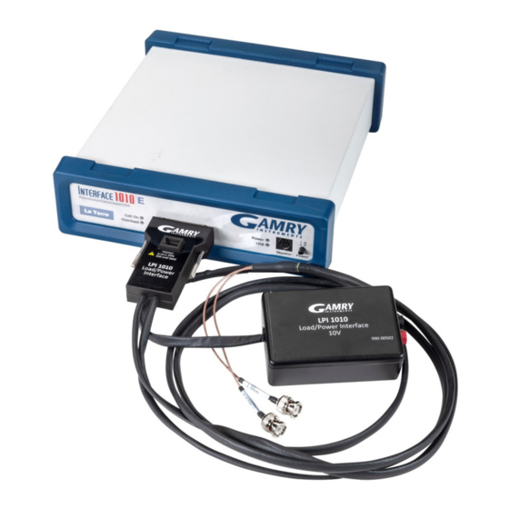
- Page 1 Load/Power Supply Interface (LPI1010) High Voltage EIS Test System Operator’s Manual Copyright 2021 Gamry Instruments, Inc. Revision 1.1 August 11, 2021 Gamry P/N 988-00076...
- Page 3 Voltage EIS Test System, please try to call from a phone next to your computer, where you can type and read the screen while talking to us. We will be happy to provide a reasonable level of free support for registered users of the LPI1010 system. Reasonable support includes telephone assistance covering the normal installation, use, and simple customization ®...
- Page 4 Limited Warranty Gamry Instruments, Inc. warrants to the original user of this product that it shall be free of defects resulting from faulty manufacture of the product or its components for a period of two years from the original shipment date of your purchase.
- Page 5 Disclaimers Gamry Instruments, Inc. cannot guarantee that the Load/Power Supply Interface (LPI1010) High Voltage EIS Test System will work with all computer systems, operating systems, and third-party software applications, hardware, or software. The information in this manual has been carefully checked and is believed to be accurate as of the time of release.
-
Page 7: Table Of Contents
Configure Electronic Load or Programmable Power Supply settings in Framework ....4-7 Chapter 5: Calibration ..........................5-1 Introduction..........................5-1 Procedure to Calibrate the LPI1010 .................... 5-2 Chapter 6: Adding a new Load/Power Supply to Framework ..............6-1 Introduction..........................6-1 File Format..........................6-1 Sections ......................... - Page 8 [CalSignalOffsetIRangeX] ....................6-15 [CalDDSOffset] ......................6-17 [AppliedDCTest] ......................6-19 [CalSysACCorIRangeX] ....................6-21 [CalSGGerrIRangeX] ...................... 6-23 – LPI1010 Specifications ......................I General ............................I Environmental ..........................I – Optional Adapters ....................... III Female BNC-to-Banana-Plug Adapter Cable ................III Female BNC-to-Stripped-Wire adapter ..................III –...
-
Page 9: Chapter 1: Safety Considerations
Chapter 1: Safety Considerations Chapter 1: Safety Considerations Your Load/Power Supply Interface (LPI1010) High Voltage EIS Test System has been supplied in a safe condition. This chapter of the Load/Power Supply Interface (LPI1010) High Voltage EIS Test System Operator’s Manual contains information and warnings that you must follow to ensure continued safe operation of the Load/Power Supply Interface (LPI1010) High Voltage EIS Test System. -
Page 10: Temperature And Ventilation
Warning: Never connect a Device Under Test which outputs a voltage higher than the full- scale voltage rating of the LPI1010. Doing so could pose an electric shock hazard to the user and may damage the equipment. Connect only shrouded banana plugs into the Cable End banana receptacles. Gamry Instruments, Inc. -
Page 11: Environmental Limits
It has been subjected to environmental stress (corrosive atmosphere, fire, etc.). Do not use your LPI1010 or any other apparatus if you think it could be hazardous. Have it checked by qualified service personnel. Caution: If any part of the wiring, connectors, or enclosures on the LPI 1010 appears physically damaged, do not use the LPI cable. -
Page 12: Rf Warning
RF Warning The LPI1010 has been tested for both radiated and conducted RF interference and for immunity to RF fields, and has been found to be in compliance with FCC Part 18 and EU Council Directive 2014/30/EU, the EMC Directive EN 61326:2013—Electrical equipment for measurement, control, and laboratory use—EMC Requirements. -
Page 13: Ce Compliance
Gamry Instruments, Inc. has designed and tested the LPI1010 to comply with these standards. The relevant CE regulations include EN 61010-1:2010 and EN 61326-1:2013. RoHS Compliance The LPI1010 is built using lead-free components and lead-free solder. It complies with the European RoHS initiative. -
Page 15: Chapter 2: Introduction
The LPI1010 system enables monitoring and testing of DUTs as single cells or as stacks with voltages of up to 1000 V. Depending on model of the LPI1010, voltages of up to 10 V, 100 V, and 1000 V can be operated with the help of an electronic load or programmable power supply. -
Page 16: Notational Conventions
In order to make this manual more readable we have adopted some notational conventions. These are used throughout this manual and all other Gamry Instruments manuals: Numbered lists. A numbered list is reserved for step-by-step procedures, with the steps always performed ... -
Page 17: Chapter 3: Installation
Verify that all parts listed on the packing list are included. Be sure you have the correct version of your LPI1010. Compare the packing list with the label on the D-sub Module and Cable End Module. Below are the variants of the... -
Page 18: Physical Location
The LPI1010 does not have active cooling. If you place your LPI1010 within an enclosed space, make sure that the internal temperature within that space does not exceed 45C, the maximum ambient temperature for the LPI1010. -
Page 19: Reboot Your Computer After Software Installation
Reboot Your Computer after Software Installation Reboot your computer when the Gamry Setup program is done. The Setup program normally offers you the opportunity to do so. Following Setup, you may not be able to use your LPI1010 until the drivers are loaded. ®... -
Page 20: Firmware Update
Firmware Update Before using your LPI1010 system, verify that you have the latest firmware installed. The LPI1010 itself does not have a firmware but the Interface 1010 potentiostat used with it does. From time to time, Gamry Instruments makes changes to the instrument’s firmware code and a firmware update is required to make use of the new or... -
Page 21: Chapter 4: Hardware Installation
DUT. The LPI1010 serves as active link between potentiostat, electronic load, and DUT. It is under control of an external computer which runs the applications of Gamry Instruments’ Framework software. -
Page 22: Signal Processing
Chapter 4: Hardware Installation Figure 4-1 Typical Electrochemical Test Setup using the LPI1010 Signal Processing Both the Electronic Load and Programmable Power Supply must have inputs for controlling the DUT current and outputs proportional to the actual DUT current. As mentioned in the system description, the Cable End Module accepts the raw DUT voltage and divides it down before feeding that signal to the LPI D-sub Module. -
Page 23: Install The Interface 1010 Potentiostat
10 V LPI cable divides it by 1. This 0 to ±10 V signal (full-scale), shown as “LV” in the block diagram of Appendix C, is fed by a coax cable to the LPI1010 D-sub Module. The “LV” signal is buffered by unity-gain amplifiers in the LPI D-sub Module and fed differentially into the Reference Electrode and Work Sense Electrode of the Interface 1010 cell connector. -
Page 24: Lpi Power Cable And Power Connection
LPI Power Cable and Power Connection The LPI1010 is indirectly powered using the potentiostat’s User I/O connector. It supplies 5 V to the female micro USB-B connector on the D-sub Module. Gamry Instruments guarantees proper performance only using its supplied power cable (P/N 985-00197), see Figure 4-3. -
Page 25: Connect Current Monitor And Current Control Cables
Schematic overview of current control (I_CTRL) and current monitor (I_MON) cable installation The red-marked BNC connector lead is the current control (I_CTRL) output of the LPI1010 and goes to the mating current control input of the electronic load or programmable power supply. The black-marked BNC connector lead serves as current monitor (I_MON) of the LPI1010 and connects to the current monitor output of the electronic load or programmable power supply. -
Page 26: Connect Cell Cables To Dut
The other end of the LPI Voltage Sense Cable is connected to the DUT. Connect Cell Cables to DUT After installing the LPI1010 to the potentiostat and all other cables to the LPI1010 and the electronic load or power supply, the DUT can be connected to the setup as shown in Figure 4-8. -
Page 27: Configure Electronic Load Or Programmable Power Supply Settings
Configure Electronic Load or Programmable Power Supply settings After finishing the installation of the LPI1010 and Interface 1010 and before running any actual experiments with a DUT, the hardware settings of the electronic load or programmable power supply need to be checked. Due to the large variety of electronic loads and programmable power supplies on the market, this section discusses the configuration only in a general terms. - Page 28 The setup configuration of the electronic load or programmable power supply MUST be entered in Framework before the first use of your LPI1010 system. 1) Ensure that your LPI1010 is plugged into the Interface 1010 instrument, and the LPI1010 has its power cable connected to the back of the Interface 1010 2) Power on your Interface 1010 and ensure that its USB port is connected to your computer 3) Start the Gamry Instrument Manager from either the Start menu or from within the Framework™...
- Page 29 Full Scale Input / The value of the measurement full-scale voltage is entered in the Full Scale Input field. The value of the control full scale is entered in the Full Scale Output. The LPI1010 can Full Scale Output use voltages between +1 V and +10 V for either of these fields.
- Page 30 Chapter 4: Hardware Installation 4-10...
-
Page 31: Chapter 5: Calibration
It is recommended calibrating your instrument at least once a year. Before calibrating the LPI1010, please make sure that your Interface 1010 is fully calibrated or calibrate it first if required. -
Page 32: Procedure To Calibrate The Lpi1010
The standard LPI1010 calibration calls for an external resistive dumm cell. Your LPI1010 system was shipped with two Calibration Cells, which include a 200 mΩ (5% accuracy) and 2 Ω (5% accuracy) resistor. After calibration, please place this dummy cell in a safe place where you can find it if your unit requires recalibration. - Page 33 Chapter 5: Calibration 3) Verify that all settings for the electronic load or programmable power supply in the LPI Configuration Entry setup window are correct. 4) Open Gamry Framework™ software and open the LPI calibration experiment using one of the methods discussed in the previous section 5) The LPI Calibration window appears, see Figure 5-4.
- Page 34 Connect the LPI Voltage Sense Cables to the banana connectors. Click the OK button to continue. Figure 5-7 LPI1010 200 mΩ Calibration Cell with connected cell leads Caution: After attaching all cables to the calibration cell and before continuing with the calibration, put the safety cover back on and secure it.
- Page 35 Figure 5-10 Completed Calibration The LPI1010 D-sub Module contains an EEPROM memory chip. All cell cables with EEPROM memory are known as dynamic cables. After performing a calibration, the calibration results are stored in the cable. You can also see all calibration results in the Calibration pane at the bottom of the Gamry Instrument...
-
Page 37: Chapter 6: Adding A New Load/Power Supply To Framework
The PD Info file is a settings file that describes the ranges and workings of an electronic load or programmable power supply. This file is used in the configuration of a Gamry LPI1010 instrument. The PD Info file is an ASCII text file that is formatted in the fashion of an *.INI file. -
Page 38: File Name
File Name Descriptive Text Each PD Info file can have descriptive text AFTER the required ‘LPI1010 PDxxxx Setting File’ text. In the example below, the descriptive text helps identify that this is a PD Info file for a NF BP 4610 power supply (‘for NF BP4610’). -
Page 39: Required Sections
Chapter 6: Adding a new Load/Power Supply to Framework Required Sections In order for a PD Info file to be properly interpreted by the Gamry software, specific section are required within the file. If the file is missing one of these sections or a section is missing required information, the software will be unable to load the file and not be able to be used by the system. - Page 40 Chapter 6: Adding a new Load/Power Supply to Framework Key Name Type Required Description This is the name that is shown by the software when DeviceName String referencing the device. This is the unique four-digit ID that is in the file name. These two numbers must match.
-
Page 41: [Devicestrings]
Chapter 6: Adding a new Load/Power Supply to Framework [DeviceStrings] The [DeviceStrings] section contains informational strings used to display messages to the user. Each message can contain a variable number of lines of information to be displayed. The number of lines is specified by the NameStringCount entry, where Name is the string identifier. - Page 42 Chapter 6: Adding a new Load/Power Supply to Framework Key Name Type Required Description This is the count for the number of lines of Safety SafetyStringCount Integer strings. One or more safety strings. The safety strings are shown every time the device is used. It should contain SafetyStringX String cautionary information about voltages and safety.
-
Page 43: [Irangex]
Chapter 6: Adding a new Load/Power Supply to Framework [IRangeX] The [IRangeX] section provides information about the current ranges for the power device in use. Depending on the number of available current ranges, one or more IRange sections for the power device are required. The number of sections has to match the number of current ranges for the power device. - Page 44 Chapter 6: Adding a new Load/Power Supply to Framework Key Name Type Required Description This is the maximum current, in Amps, for the current RangeMaxI Float range. This is the voltage, in Volts, that is output from the RangeMaxVin Float current monitor when the power device is at maximum current.
-
Page 45: Optional Sections
Chapter 6: Adding a new Load/Power Supply to Framework Optional Sections [CalFrontEndOfst] This section is used during calibration for the Front End channel offsets. The cell is not turned on, so the value of the resistor is not extremely important. The example depicts the information for a BP4610 power supply from NF Corporation. - Page 46 Chapter 6: Adding a new Load/Power Supply to Framework Key Name Type Required Description CalCellValue Float This is the calibration cell value, in ohms. This is the description of the calibration cell which is CalCell String used to tell the user what connection to make. This is the voltage, in volts, used to set the Vch range on VchRange Float...
-
Page 47: [Calelgerr]
Chapter 6: Adding a new Load/Power Supply to Framework [CalELGerr] This section is used during calibration of the Electrometer gain. The cell should be selected to produce a mid-range voltage for the power device. Normally, the LPI is selected to have a similar voltage range to the power device. Make sure the voltage produced is within the capability of both the power device and the LPI. - Page 48 Chapter 6: Adding a new Load/Power Supply to Framework Key Name Type Required Description CalCellValue Float This is the calibration cell value, in ohms. This is the description of the calibration cell which is CalCell String used to tell the user what connection to make. This is the voltage, in volts, used to set the Vch range on VchRange Float...
-
Page 49: [Caliegerrirangex]
Chapter 6: Adding a new Load/Power Supply to Framework [CalIEGerrIRangeX] There are one or more sections used during calibration of the IERange gain. The number of sections has to be equal to the number of current ranges on the power device. The cell should be selected to produce a mid-range voltage for the power device. - Page 50 Chapter 6: Adding a new Load/Power Supply to Framework Key Name Type Required Description CalCellValue Float This is the calibration cell value, in ohms. This is the description of the calibration cell which is CalCell String used to tell the user what connection to make. This is the voltage, in volts, used to set the Vch range on VchRange Float...
-
Page 51: [Calsignaloffsetirangex]
Chapter 6: Adding a new Load/Power Supply to Framework [CalSignalOffsetIRangeX] There are one or more sections used during calibration of the Signal offset. The number of sections has to be equal the number of current ranges on the power device. The example bewow depicts the information for a BP4610 power supply from NF Corporation which has a single 10 A current range. - Page 52 Chapter 6: Adding a new Load/Power Supply to Framework Key Name Type Required Description CalCellValue Float This is the calibration cell value, in ohms. This is the description of the calibration cell which is CalCell String used to tell the user what connection to make. This is the voltage, in volts, used to set the Vch range on VchRange Float...
-
Page 53: [Calddsoffset]
Chapter 6: Adding a new Load/Power Supply to Framework [CalDDSOffset] This section is used during calibration of the DDS offset. The cell should be selected to produce a mid-range voltage for the power device. Normally, the LPI is selected to have a similar voltage range to the power device. Make sure the voltage produced is within the capability of both the power device and the LPI. - Page 54 Chapter 6: Adding a new Load/Power Supply to Framework Key Name Type Required Description CalCellValue Float This is the calibration cell value, in ohms. This is the description of the calibration cell which is CalCell String used to tell the user what connection to make. This is the voltage, in volts, used to set the Vch range on VchRange Float...
-
Page 55: [Applieddctest]
Chapter 6: Adding a new Load/Power Supply to Framework [AppliedDCTest] This section is used during calibration to confirm the application of DC values to the cell. Nothing is calibrated during this step, rather it is just a check to confirm expected DC levels. Make sure the voltage produced is within the capability of both the power device and the LPI. - Page 56 Chapter 6: Adding a new Load/Power Supply to Framework Key Name Type Required Description CalCellValue Float This is the calibration cell value, in ohms. This is the description of the calibration cell which is CalCell String used to tell the user what connection to make. This is the voltage, in volts, used to set the Vch range on the IFC1010 instrument.
-
Page 57: [Calsysaccorirangex]
Chapter 6: Adding a new Load/Power Supply to Framework [CalSysACCorIRangeX] There are one or more sections used during calibration based on the number of ranges for the power device. This section is used during calibration to measure the AC response of the entire system and to correct the system for a neutral response as much as possible. - Page 58 Chapter 6: Adding a new Load/Power Supply to Framework Key Name Type Required Description CalCellValue Float This is the calibration cell value, in ohms. This is the description of the calibration cell which is CalCell String used to tell the user what connection to make. This is the voltage, in volts, used to set the Vch range on the IFC1010 instrument.
-
Page 59: [Calsggerrirangex]
Chapter 6: Adding a new Load/Power Supply to Framework [CalSGGerrIRangeX] There are one or more sections used during calibration of the Signal Generator gain. The number of sections has to be equal the number of current ranges on the power device. The cell should be selected to produce a mid-range voltage for the power device. - Page 60 Chapter 6: Adding a new Load/Power Supply to Framework Key Name Type Required Description CalCellValue Float This is the calibration cell value, in ohms. This is the description of the calibration cell which is CalCell String used to tell the user what connection to make. This is the voltage, in volts, used to set the Vch range on VchRange Float...
-
Page 61: Lpi1010 Specifications
NOTES: 1. Measured between ground and each leg. 2. AC CMRR measured at 20 kHz for 100V Std and 100 V NF LPI1010 system. AC CMRR measured at 10 kHz for 1KV LPI1010 system. 3. Measured between BNC shell and center pin. -
Page 63: Optional Adapters
Due to the large variety of electronic loads and programmable power supplies on the market, the BNC connectors at the current monitor and current control cables of the LPI Cable End Module might not be suitable. For this, Gamry Instruments offers various adapter cables. Female BNC-to-Banana-Plug Adapter Cable A Female BNC-to-Banana Plug adapter cable is available as an option as shown below. -
Page 65: Block Diagram
Appendix C– Block diagram – Block diagram Figure C-1 Female BNC-to-Stripped Wire adapter cable (P/N 721-00019) USB Cable Host Computer LPI Power Cable (Gamry P/N 985-00197) LPI D-sub Module LPI Cable End Electronic Load Module or Programmable Power Supply Appendix C - V... -
Page 67: Certificate Of Conformity
Appendix D– Certificate of conformity – Certificate of conformity Appendix D - VII... - Page 68 Appendix D– Certificate of conformity Appendix D - VIII...
-
Page 69: Index
Index Index calibration ........5-1, 5-2, 5-3, 5-5 operation............1-3 CE Certificate ............VII Options menu ............ 3-3 CE Compliance ............ 1-5 passive cooling ........... 1-2 cleaning .............. 1-3 Power Device Info file ......4-9, 6-1, 6-2 computer ..iii, v, 1-4, 2-2, 3-1, 3-2, 3-3, 3-4, 4-1 power line transient ...........
Need help?
Do you have a question about the LPI1010 and is the answer not in the manual?
Questions and answers