Table of Contents
Advertisement
Quick Links
Advertisement
Table of Contents

Related Manuals for optris PROFIBUS-DP-V1

Summary of Contents for optris PROFIBUS-DP-V1
- Page 1 Operator‘s Manual optris ® PROFIBUS Interface for optris CT infrared thermometers...
- Page 2 Optris GmbH Ferdinand-Buisson-Str. 14 13127 Berlin Germany Tel.: +49 30 500 197-0 Fax: +49 30 500 197-10 E-mail: info@optris.global Internet: www.optris.global...
-
Page 3: Table Of Contents
Installation / Interfaces ..........................8 Setting PROFIBUS address at optris CT ..................9 Information regarding GSD file ......................9 Operation of optris CT with the PROFIBUS-DP-V1 interface ............10 Data conversion ..........................10 Operation of CT mainboard ........................11 PROFIBUS DP............................12... - Page 4 DP startup ............................12 4.1.1 Parameter data .......................... 12 4.1.2 Configuration data ........................13 4.1.3 Diagnosis data ........................... 13 Cyclic data transfer ......................... 13 4.2.1 Diagnosis during cyclic data transfer ..................14 Synchronization of sync and freeze ....................14 State of things within the master ....................14 State machinery within the slave ....................
- Page 5 Table of Contents 4.9.2 Module internal sensing head temperature ................23 4.9.3 Module telegram ........................24 DP-V1 – Acyclic data transfer ......................26 4.10 4.10.1 DP-V1 interface ........................26 4.10.2 Data of the couple (Slot_Number = 0) ................... 27 4.10.3 Data for function modules ......................
-
Page 6: General Information
1 General Information 1.1 Description Thank you for choosing optris ® PROFIBUS-DP-V1 interface. The PROFIBUS (Process Field Bus) is a fieldbus communication which is used for data exchange in the field plane. Read the manual carefully before the initial start-up. The producer reserves the right to change the herein described specifications in case of technical advance of the product. -
Page 7: Scope Of Supply
General Information 1.3 Scope of supply ▪ PROFIBUS-DP-V1 interface ▪ M12 device socket ▪ Cable connection M12x1,5 ▪ 2 screws M3x5 ▪ Software CD (operators manual, GSD file) ▪ Brief instruction... -
Page 8: Installation / Interfaces
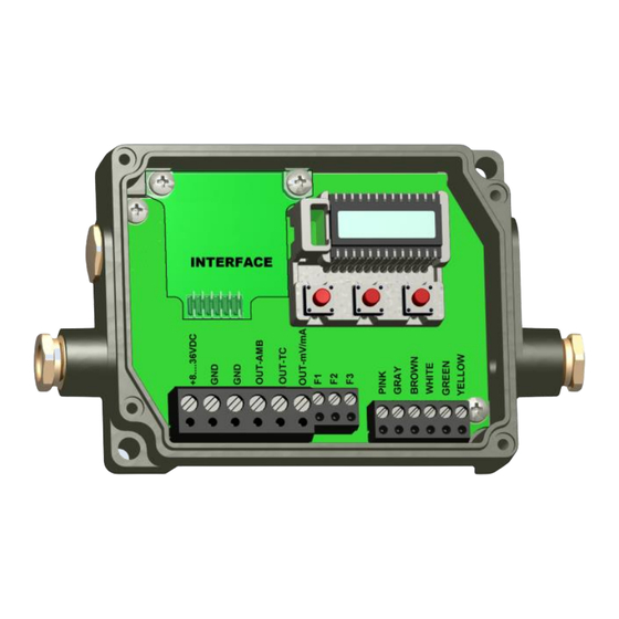
Please install the M12 device socket onto the lower left and the cable connection onto the upper left position of the CT box. Plug the PROFIBUS-DP-V1 interface into the intended plug at the CT which is right next to the display. Push down the PROFIBUS-DP-V1 interface and adjust it with the supplied screws M3x5 within the electronic box. -
Page 9: Setting Profibus Address At Optris Ct
“SL001” appears. Afterwards the favored slave address will be chosen with the „UP” and “DOWN” buttons – this will be taken over after six seconds. Then the optris CT has to be removed from the voltage for three seconds. -
Page 10: Operation Of Optris Ct With The Profibus-Dp-V1 Interface
After the GSD file (IT010A90.gsd) has been read into the configuration tool and transferred to the master, the optris CT with PROFIBUS-DP-V1 interface is ready for data exchange. This can also be seen on the green LED on the Profibus-DP-V1 interface, if the cover was removed from the optris CT (open only for testing purposes). -
Page 11: Operation Of Ct Mainboard
Operation of CT mainboard 3 Operation of CT mainboard The sensor configuration will be done with the three control keys Mode, Up and Down. Display example Mode Explanation Object temperature ref. to signal (here: 35,2 °C) Head temperature (here: 26,3 °C) Temperature electronic box (here: 38,0 °C) Effective object temperature (here: 34,0 °C) Signal output entrance cable 1 (here: 0-5 V) -
Page 12: Profibus Dp
4 PROFIBUS DP Within PROFIBUS DP systems, the master (PLC, PC, etc.) generally communicates with many slaves (IO, drive, etc.) whereas only the master can access the bus (sent unasked telegrams) while a DP slave only sends telegrams if it has been requested by a master. 4.1 DP startup Before master and slave cyclically exchange data with each other, the parameter and configuration data are transferred from the master to the slaves during the DP startup. -
Page 13: Configuration Data
PROFIBUS DP 4.1.2 Configuration data The configuration data are sent from the master to the slaves with the ChkCfg request telegram; the ChkCfg response telegram contains no data and therefore consists of only one byte, the short acknowledgment. The configuration data describe the assignment of the DP modules to the cyclic IO data that is exchanged with the Data_Exchange telegram during the cyclic data exchange between master and slave. -
Page 14: Diagnosis During Cyclic Data Transfer
4.2.1 Diagnosis during cyclic data transfer During cyclic data exchange, a slave can report a diagnosis to the master. In this case, the slave sets a flag in the DataExchange response telegram; whereupon the master recognizes that the slave has new diagnostics data, which he then picks up with the SlaveDiag telegram. -
Page 15: State Machinery Within The Slave
PROFIBUS DP 4.5 State machinery within the slave... -
Page 16: Dp Master Class 1 And Class 2
2 master is a B&B device that generally only reads the slaves IO data in a read-only manner. PROFIBUS-DP-V1 essentially refers to the acyclic read and write telegrams used to acyclic access data records in the slave. With DP-V1 as well, a distinction is made between class 1 and a class 2 master. The acyclic class 1 (C1) or class 2 (C2) connection differ in that the acyclic C1 connection is established with the DP startup of the cyclic DP operation. -
Page 17: Profibus Access
PROFIBUS DP 4.7 PROFIBUS access M12 device socket The M12 device socket is coded inversely and has 5 pins. Pin 1 and pin 2 transmit the signals of the Profibus. These must under no circumstances be exchanged, otherwise the communication is disturbed. Pin 2 transmits +5 VDC and Pin 4 transmits GND for the active terminator. -
Page 18: Userprmdata In Head Station
4.8 UserPrmData in head station Within the UserPrmData of the head station, the following settings can be done: Byte Data Description DP-V1-operation logged DP-V1-operation free for use Fail-Safe-Mode is not supported Fail-Safe-Mode is supported Publisher-Mode is not supported Publisher-Mode is supported WD-Time-Base 10ms WD-Time-Base 1ms DP-V1: process alarm is not supported... - Page 19 PROFIBUS DP DP-V0: Diagnoses alarm is supported Release channel-related diagnostics Disable channel-related diagnostics Release module status Disable module status Release identifier-related diagnostics Disable identifier-related diagnostics Status alarm clear Status alarm locked 9,10 Emissivity 11,12 Transmission ratio 13,14 Averaging time 15,16 Hold time 17,18 Threshold level 1...
-
Page 21: Configuration - Cfgdata
PROFIBUS DP 4.9 Configuration – CfgData The CfgData are formed from the modules added in the DP configuration tool. When attaching the modules, the following rules must be observed: - each module is allowed to be plugged only once - the sequence of the module is unimportant - at least one module needs to be plugged... -
Page 22: Module Object Temperature
4.9.1 Module object temperature Byte Data Description 0x0A Parameter data length Slot number 0x01 Module identification DP-V0: Process alarm not supported DP-V0: Process alarm supported Reserved Maximum boundary value Minimum boundary value... -
Page 23: Module Internal Sensing Head Temperature
PROFIBUS DP 4.9.2 Module internal sensing head temperature Byte Data Description 0x0A Parameter data length Slot number 0x02 Module identification DP-V0: Process alarm not supported DP-V0: Process alarm supported Reserved Maximum boundary value Minimum boundary value... -
Page 24: Module Telegram
4.9.3 Module telegram Used for transferring the Optris special commands: Data from Master → Slave Byte Description Handshake Data0 Data1 Data2 Data3 Data4 Data5 Data6 Data7 Data8... - Page 25 PROFIBUS DP Data from Slave → Master Byte Description 15hex: length of telegram, receive telegram – F1hex: Timeout no telegram received Handshake Data0 Data1 Data2 Data3 Data4 Data5 Data6 Data7 Data8 Data9 Data10 Data11 Data12 Data13 Data14 Data15 Data16 Data17 Data18 Data19 Data20...
-
Page 26: Dp-V1 - Acyclic Data Transfer
4.10 DP-V1 – Acyclic data transfer 4.10.1 DP-V1 interface By default, one MSAC_C1 and three MSAC_C2 connections each with 244 bytes of data (4 bytes DPv1 header plus 240 bytes of user data) are supported. The MSAC_C1 connection is established together with the cyclic connection and must be activated via the UserPrmData: Byte Data... -
Page 27: Data Of The Couple (Slot_Number = 0)
The data of the coupler are addressed via an index. Index Access Data length Description Parameter: Emissivity Transmission ratio Average time Hold time Signal threshold Emissivity Transmission ratio Averaging time Hold time Signal threshold 1 Status alarm Optris special commands Data0 Data1 Data2 Data3 Data4 Data5 Data6 Data7 Data8... - Page 28 Data0 Data1 Data2 Data3 Data4 Data5 Data6 Data7 Data8 Data9 Data10 Data11 Data12 Data13 Data14 Data15 Data16 Data17 Data18 Data19 Data20 I&M-data record 0...
-
Page 29: Data For Function Modules
PROFIBUS DP 4.10.3 Data for function modules Object temperature: Index Access Data length Description 0x00 Module parameter: Byte0: Process alarm Byte1: Reserved Byte2: Reserved Byte3,4: maximum boundary value Byte5,6: minimum boundary value 0x01 Byte0,1: Measurement value Internal sensing head temperature: Index Access Data length... -
Page 30: Dp Diagnosis
4.11 DP diagnosis DP diagnosis data (DiagData) The DP diagnostics data consists of 6 bytes DP standard diagnostics and up to 33 bytes of device-specific diagnostics data. If the DP diagnostic data changes, the slave reports this to the master, which then automatically fetches the changed diagnostic data automatically. -
Page 31: Module Status
PROFIBUS DP Bit 0: Entry for sensing head module Bit 1: Entry for module at slot 1 0x01 Bit 2: Entry for module at slot 2 Bit 3: Entry for module at slot 3 4.11.2 Module status The module status reflects the status of the configured assembly group and represents a detail of the identifier-related diagnostics with regard to the configuration. -
Page 32: Channel-Related Diagnosis
Bit combinations: 00 B : Assembly group ok; valid data 01 B : Assembly group bug; invalid data (assembly group defect) 10 B : Wrong assembly group; invalid data 11 B : No assembly group; invalid data 4.11.3 Channel-related diagnosis The channel-related diagnostics provide information about channel errors of modules and provide a detail of the identifier-related diagnostics. -
Page 33: Process Alarm
PROFIBUS DP The following Error-Codes are supported (defined in the GSD file): Channel_Diag(16) = "Target: Temperature too high" Channel_Diag(23)= "Sensing head: Temperature too high" Channel_Diag(17) = "Target: Temperature too low" Channel_Diag(24)= "Sensing head: cable defect" Channel_Diag(18) = "Box: Temperature to low" Channel_Diag(25)= "Sensing head: Short circuit"... -
Page 34: Diagnoses Alarm
4.11.5 Diagnoses alarm The diagnoses alarm for Optris0A90 is set up as follows: Byte Data Description 0x00 0x06 Header 0x01 0x01 Diagnoses alarm 0x02 0x00 Head station 0x00 0x01 : Coming result 0x03 0x02 : Leaving result Error Bit 0: Assembly group disruption 0x04 Bit 1: Internal error Bit 2: External error... -
Page 35: Appendix A - Declaration Of Conformity
Appendix A – Declaration of Conformity Appendix A – Declaration of Conformity EU Declaration The product meets the provisions of the EMC Directive 2014/30/EU and the General Product Safety Directive 2001/95/EC. EMC General Requirements: EN 61326-1:2013 (Basic requirements) EN 61326-2-3:2013 Safety of measurement devices: EN 61010-1:2010 This product is in conformity with Directive 2015/863/EU (RoHS) of...
Need help?
Do you have a question about the PROFIBUS-DP-V1 and is the answer not in the manual?
Questions and answers