
Related Manuals for Littlefuse PGR-6150 Series

Summary of Contents for Littlefuse PGR-6150 Series
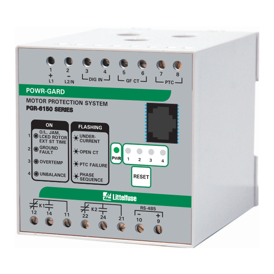
- Page 1 ® POWR-GARD Motor Protection PGR-6150 SERIES Motor Protection System PGR-6150 Motor Protection System September 29, 2010 REVISION 1...
- Page 2 PGR-6150 Motor Protection System Rev. 1 _________________________________________________________________________________...
-
Page 3: Table Of Contents
PGR-6150 Motor Protection System Rev. 1 _________________________________________________________________________________ 1. GENERAL HANDLING .................... 1.1. Unpacking and Inspection ......................5 1.2. Handling Electronic Equipment ..................... 5 1.3. Installation ............................. 5 1.4. Storage ............................5 2. DIMENSIONS ......................2.1. PGR-6150 ............................. 6 2.2. PGR-6150-OPI ..........................7 3. - Page 4 PGR-6150 Motor Protection System Rev. 1 _________________________________________________________________________________ 6.3.11. Digital Input ......................... 46 6.3.12. Outputs ..........................46 6.3.13. PGR-6150 Base Module LED’s ................... 47 6.3.14. Adjustable PGR-6150-OPI LED’s ..................47 6.3.15. Self-Diagnostics ........................49 6.3.16. Date-Time Synchronization ....................49 6.3.17. RS-485 Communications ....................49 6.3.18.
-
Page 5: General Handling
PGR-6150 Motor Protection System Rev. 1 _________________________________________________________________________________ 1. GENERAL HANDLING 1.1. Unpacking and Inspection The PGR-6150 must only be handled by qualified personnel and special care must be taken to protect its parts from damage during unpacking and installation. Inspect the PGR-6150 at delivery to ensure no damage occurred during transport. Inform Littelfuse Inc. -
Page 6: Dimensions
PGR-6150 Motor Protection System Rev. 1 _________________________________________________________________________________ 2. DIMENSIONS 2.1. PGR-6150 56.5 (2.22) ø10 (ø0.39) 33.0 (1.30) TOP VIEW 99.0 (3.90) NOTES: DIMENSIONS IN MILLIMETRES (INCHES). 94.0 (3.70) (0.20) SIDE VIEW... -
Page 7: Pgr-6150-Opi
PGR-6150 Motor Protection System Rev. 1 _________________________________________________________________________________ 2.2. PGR-6150-OPI 122.5 (4.82) 100.0 (3.94) 106.0 (4.17) TOP VIEW ALTERNATE CLAMP LOCATIONS NOTES: DIMENSIONS IN MILLIMETRES (INCHES). FRONT VIEW... -
Page 8: Connection Diagrams
PGR-6150 Motor Protection System Rev. 1 _________________________________________________________________________________ 3. CONNECTION DIAGRAMS 3.1. Direct Connection MOTOR AUX VOLTAGE GF CT SUPPLY TRIP START STOP PGR-6150 ALARM 3.2. Multiple Pass Connection MOTOR AUX VOLTAGE GF CT SUPPLY TRIP START STOP PGR-6150 ALARM For motors with nominal current below the minimum relay set-point value, multiple turns can be used. -
Page 9: External Ct Connection
PGR-6150 Motor Protection System Rev. 1 _________________________________________________________________________________ 3.3. External CT Connection AUX VOLTAGE GF CT SUPPLY TRIP START STOP PGR-6150 ALARM For motors with nominal current over the maximum relay current set-point value, combine the relay with current transformers. Set the value I and CT Turns Ratio as explained in Section 6.2.1. -
Page 10: Pgr-6150 Base-Module Terminals
PGR-6150 Motor Protection System Rev. 1 _________________________________________________________________________________ 4. PGR-6150 BASE-MODULE TERMINALS DIG IN 24 Vac/dc digital input GF CT Ground-fault current transformer connection PTC temperature sensor connection RS-485 connection + RS-485 connection - Output K1 contact normally open Output K1 contact normally closed Output K1 common Output K2 contact normally open Output K2 contact normally closed... -
Page 11: Description
PGR-6150 Motor Protection System Rev. 1 _________________________________________________________________________________ 5. DESCRIPTION 5.1. General The PGR-6150 is a modular system that provides integrated protection, metering and data logging functions. The PGR-6150 base module can operate as a stand-alone unit or with the operator interface PGR-6150-OPI, the voltage module PGA-0160, and the input/output module PGA-0180. -
Page 12: Inputs And Outputs
PGR-6150 Motor Protection System Rev. 1 _________________________________________________________________________________ 5.2.4. Inputs and Outputs • One digital input • One trip output relay • One alarm output relay • PTC input • Ground-fault current transformer input • Relay closing time delay • RJ-45 24 Vdc output to PGR-6150-OPI and optional voltage and input/output modules •... -
Page 13: Pgr-6150 Protective Functions And Control
PGR-6150 Motor Protection System Rev. 1 _________________________________________________________________________________ 6. PGR-6150 PROTECTIVE FUNCTIONS AND CONTROL 6.1. Power Supply • The PGR-6150 comes with a 110/240 Vac/dc, 5 W power supply. The PGR-6150 generates 24 Vdc available through the RJ-45 port to supply auxiliary modules. 6.2. -
Page 14: Overload
PGR-6150 Motor Protection System Rev. 1 _________________________________________________________________________________ 6.2.2. Overload The overload function meets international standard IEC 947-4-1 and IEC 255-8. A mathematically based thermal model is used to simulate the motor's thermal condition. The model combines two thermal images: A heating image and a cooling image. The heating image represents the thermal condition of the windings of the stator and rotor, and the cooling image represents the thermal condition of the motor housing. -
Page 15: Phase Unbalance
PGR-6150 Motor Protection System Rev. 1 _________________________________________________________________________________ The PGR-6150 allows for overload function settings between 1 and 2 times I . Note however that standard IEC-947-4-1 recommends the tap setting to be between 1.05 and 1.20 times I 6.2.3. Phase Unbalance The unbalance function is applied on a three phase system made up of three phase currents (IA, IB, IC). -
Page 16: Phase Sequence
PGR-6150 Motor Protection System Rev. 1 _________________________________________________________________________________ There is only one operating time, regardless of whether the motor is starting up or in operation. Phase loss Description Minimum Maximum Step Unit Default Function enabled yes/no % Unbalance (d2) Time 0.02 0.001 6.2.5. -
Page 17: Jam
PGR-6150 Motor Protection System Rev. 1 _________________________________________________________________________________ Description Minimum Maximum Step Unit Default Function enabled yes/no The trip time is 500 ms. The PTC sensor current is 1 mA and a maximum of 2.3 V is used. Maximum cold resistance 1,500 Ω... -
Page 18: Calculated Definite-Time Ground Fault
PGR-6150 Motor Protection System Rev. 1 _________________________________________________________________________________ 6.2.9. Calculated Definite-Time Ground Fault This function detects motor ground-fault current based on phase currents. >> GF CALC DEF Description Minimum Maximum Step Unit Default Function enabled yes/no Pickup 0.01 Time 0.02 0.001 This function is enabled after the motor start-up sequence has been completed. -
Page 19: Measured Definite-Time Ground Fault
PGR-6150 Motor Protection System Rev. 1 _________________________________________________________________________________ 6.2.11. Measured Definite-Time Ground Fault This option requires a ground-fault current transformer. >> GF MEASURED DEF Description Minimum Maximum Step Unit Default Function enabled yes/no Pickup 15,000 Time 0.02 0.001 This function is enabled after the motor start-up sequence has been completed. Section 6.2.14 6.2.12. -
Page 20: Undercurrent
PGR-6150 Motor Protection System Rev. 1 _________________________________________________________________________________ 6.2.13. Undercurrent The undercurrent function is not enabled during motor start-up. I < Undercurrent Description Minimum Maximum Step Unit Default Function enabled yes/no Pickup 0.01 Time 0.02 0.001 Activation is at 100% of the pickup value and reset at 105%. The reset is instantaneous. The accuracy of the operation time is equal to the set time plus a maximum of 30 ms. -
Page 21: Pgr-6150 Settings Summary
PGR-6150 Motor Protection System Rev. 1 _________________________________________________________________________________ In “Motor first step” and “Motor second step” the start-up time is monitored. If the measured start-up time is greater than the “Motor starting time” selected, the start up will be aborted due to a “Start time exceeded”... - Page 22 PGR-6150 Motor Protection System Rev. 1 _________________________________________________________________________________ Description Minimum Maximum Step Unit Default OVERLOAD Function enabled yes/no Service factor 0.01 1.15 Trip class 5,10,15,20,25,30,35,40,45 External ventilation Yes/No Alarm UNBALANCE Function enabled yes/no % Unbalance Starting trip time 0.02 0.001 Running trip time 0.02 0.001 PHASE LOSS...
- Page 23 PGR-6150 Motor Protection System Rev. 1 _________________________________________________________________________________ Description Minimum Maximum Step Unit Default > GF CALC INVERSE Function enabled yes/no Curve (2*) Inverse Dial 0.05 1.25 0.01 1.25 Pickup 0.01 1.00 Operating time 0.02 0.001 >> GF MEASURED DEF Function enabled yes/no Pickup 15,000...
-
Page 24: Overload Curves
PGR-6150 Motor Protection System Rev. 1 _________________________________________________________________________________ 6.2.16. Overload curves The first graph shows the class 5, 10, 15, 20, 25, 30, 35, 40 and 45 trip curves starting from an initial thermal condition of 0% (cold). The following graphs show individually the class 5, 10, 15, 20, 25, 30, 35, 40 and 45 trip curves with initial thermal conditions of 0% (cold), 60% (hot 60%), 75% (hot 75%). - Page 25 PGR-6150 Motor Protection System Rev. 1 _________________________________________________________________________________ OVERLOAD (cold) 10,000 1,000 CLASS 45 CLASS 40 CLASS 35 CLASS 30 CLASS 25 CLASS 20 CLASS 15 CLASS 10 CLASS 5 1.15 I...
- Page 26 PGR-6150 Motor Protection System Rev. 1 _________________________________________________________________________________ OVERLOAD CLASS 5 10,000.0 1,000.0 100.0 COLD HOT 60% HOT 75% 10.0 Hot 60% I = 0.9I Hot 75% I = I 10.0 11.0 1.15 I...
- Page 27 PGR-6150 Motor Protection System Rev. 1 _________________________________________________________________________________ OVERLOAD CLASS 10 10,000.0 1,000.0 COLD HOT 60% HOT 75% 100.0 10.0 Hot 60% I = 0.9 I Hot 75% I = I 10.0 11.0 1.15 I...
- Page 28 PGR-6150 Motor Protection System Rev. 1 _________________________________________________________________________________ OVERLOAD CLASS 15 10,000.0 1,000.0 COLD HOT 60% HOT 75% 100.0 10.0 Hot 60% I = 0.9 I Hot 75% I = I 10.0 11.0 1.15 I...
- Page 29 PGR-6150 Motor Protection System Rev. 1 _________________________________________________________________________________ OVERLOAD CLASS 20 10,000.0 1,000.0 COLD HOT 60% HOT 75% 100.0 10.0 Hot 60% I = 0.9I Hot 75% I = I 10.0 11.0 1.15 I...
- Page 30 PGR-6150 Motor Protection System Rev. 1 _________________________________________________________________________________ OVERLOAD CLASS 25 10,000.0 1,000.0 COLD HOT 60% HOT 75% 100.0 10.0 Hot 60% I = 0.9I Hot 75% I = I 10.0 11.0 1.15 I...
- Page 31 PGR-6150 Motor Protection System Rev. 1 _________________________________________________________________________________ OVERLOAD CLASS 30 10,000.0 1,000.0 COLD HOT 60% HOT 75% 100.0 10.0 Hot 60% I = 0.9I Hot 75% I = I 10.0 11.0 1.15 I...
- Page 32 PGR-6150 Motor Protection System Rev. 1 _________________________________________________________________________________ OVERLOAD CLASS 35 10,000.0 1,000.0 COLD HOT 60% HOT 75% 100.0 10.0 Hot 60% I = 0.9I Hot 75% I = I 10.0 11.0 1.15 I...
- Page 33 PGR-6150 Motor Protection System Rev. 1 _________________________________________________________________________________ OVERLOAD CLASS 40 10,000.0 1,000.0 COLD HOT 60% 100.0 HOT 75% 10.0 Hot 60% I = 0.9 I Hot 75% I = I 10.0 11.0 1.15 I...
- Page 34 PGR-6150 Motor Protection System Rev. 1 _________________________________________________________________________________ OVERLOAD CLASS 45 10,000.0 1,000.0 COLD HOT 60% 100.0 HOT 75% 10.0 Hot 60% I = 0.9 I Hot 75% I = I 10.0 11.0 1.15 I...
-
Page 35: Iec255-4/Bs-142 Curves
PGR-6150 Motor Protection System Rev. 1 _________________________________________________________________________________ 6.2.17. IEC255-4/BS-142 Curves The PGR-6150 relay complies with the curves in Standard IEC255-4/BS-142: • Inverse Curve • Very Inverse Curve • Extremely Inverse Curve The following equation defines the time, in seconds, as a function of the current: ×... - Page 36 PGR-6150 Motor Protection System Rev. 1 _________________________________________________________________________________ IEC INVERSE 1000 Dial 1.2 Dial 1.1 Dial 1.0 Dial 0.9 Dial 0.8 Dial 0.7 Dial 0.6 Dial 0.5 Dial 0.4 Dial 0.3 Dial 0.2 Dial 0.1 Dial 0.05 0.01 10.0 100.0 CURRENT IN MULTIPLES OF PICKUP SETTING...
- Page 37 PGR-6150 Motor Protection System Rev. 1 _________________________________________________________________________________ IEC VERY INVERSE 1000 Dial 1.2 Dial 1.1 Dial 1.0 Dial 0.9 Dial 0.8 Dial 0.7 Dial 0.6 Dial 0.5 Dial 0.4 Dial 0.3 Dial 0.2 Dial 0.1 Dial 0.05 0.01 10.0 100.0 CURRENT IN MULTIPLES OF PICKUP SETTING...
- Page 38 PGR-6150 Motor Protection System Rev. 1 _________________________________________________________________________________ IEC EXTREMELY INVERSE 1000 Dial 1.2 Dial 1.1 Dial 1.0 Dial 0.9 Dial 0.8 Dial 0.7 Dial 0.6 Dial 0.5 Dial 0.4 Dial 0.3 Dial 0.2 Dial 0.1 Dial 0.05 0.01 10.0 100.0 CURRENT IN MULTIPLES OF PICKUP SETTING...
-
Page 39: Monitoring And Control
PGR-6150 Motor Protection System Rev. 1 _________________________________________________________________________________ 6.3. Monitoring and control 6.3.1. Metering The following metering options are provided: three phase currents (IA, IB, IC), neutral current (I0) calculated as a digital sum of the phase currents, ground-fault current (IG) measured by a ground-fault current transformer, positive-sequence current, negative-sequence current, average current of the three phases, thermal image measurement (%) and line frequency. -
Page 40: States
PGR-6150 Motor Protection System Rev. 1 _________________________________________________________________________________ 6.3.2. States The states are real time information regarding the state of the PGR-6150. The PGR-6150 states can be accessed through the PGR-6150-OPI and communications. All the equipment states are listed below: STATES OVERLOAD Alarm Trip... - Page 41 PGR-6150 Motor Protection System Rev. 1 _________________________________________________________________________________ STATES Phase A Trip Phase B Trip Phase C Trip Function Trip Phase A Pickup Phase B Pickup Phase C Pickup Function Pickup LOCKED ROTOR Phase A Trip Phase B Trip Phase C Trip Function Trip Phase A Pickup Phase B Pickup...
- Page 42 PGR-6150 Motor Protection System Rev. 1 _________________________________________________________________________________ STATES I < UNDERCURRENT Phase A Trip Phase B Trip Phase C Trip Function Trip Phase A Pickup Phase B Pickup Phase C Pickup Function Pickup RELAY OUTPUTS Relay K1 Relay K2 DIGITAL INPUT Input 1 MISCELLANEOUS Motor Running...
-
Page 43: Ground-Fault Current-Transformer Monitoring
PGR-6150 Motor Protection System Rev. 1 _________________________________________________________________________________ The “Equipment Alarm” consists of the following: Overload: Alarm PTC: Short-circuit PTC: Open circuit Miscellaneous: GF CT Open Miscellaneous: Settings Error Miscellaneous: Configuration Error The “Protection Trip” consists of the following: Overload: Function trip Unbalance: Function trip Phase Loss: Function trip Sequence: Function trip... -
Page 44: Reset
PGR-6150 Motor Protection System Rev. 1 _________________________________________________________________________________ 6.3.5. Reset The three reset types on the PGR-6150 are as follows: • Automatic reset • Automatic time delay reset • Manual reset If automatic reset has been selected, the PGR-6150 is reset when the trip condition is removed. If automatic time delay reset has been selected, the equipment is reset when the trip condition is removed and the reset time has elapsed. -
Page 45: Statistics
PGR-6150 Motor Protection System Rev. 1 _________________________________________________________________________________ • Jam: Phase A trip • Jam: Phase B trip • Jam: Phase C trip • Locked rotor: Phase A trip • Locked rotor: Phase B trip • Locked rotor: Phase C trip •... -
Page 46: Commands
PGR-6150 Motor Protection System Rev. 1 _________________________________________________________________________________ 6.3.10. Commands The following table lists the available commands: PGR-6150: Short press test/reset button Test LED’s PGR-6150-OPI: Short press test/reset button Communication: Control 44 PGR-6150: Test/reset button held down Outputs and LED’s reset PGR-6150-OPI: Test/reset button held down Communication: Control 47 PGR-6150-OPI: Control menu... -
Page 47: Pgr-6150 Base Module Led's
PGR-6150 Motor Protection System Rev. 1 _________________________________________________________________________________ 6.3.13. PGR-6150 Base Module LED’s Constant Equipment OK Flashing Constant Overload trip Jam trip Locked rotor trip Excessive start time Flashing Undercurrent trip Constant Ground-fault trip Flashing CT connection alarm Constant Overtemperature trip Flashing PTC failure Constant... - Page 48 PGR-6150 Motor Protection System Rev. 1 _________________________________________________________________________________ • Phase loss: Phase B pick up • Phase loss: Phase C pick up • Phase loss: Pick up • Phase loss: Phase A trip • Phase loss: Phase B trip • Phase loss: Phase C trip •...
-
Page 49: Self-Diagnostics
PGR-6150 Motor Protection System Rev. 1 _________________________________________________________________________________ 6.3.15. Self-Diagnostics Diagnostic algorithms are run continuously when the PGR-6150 is operating. The following status bits are associated with this process: Problem in the configurations saved in e2prom. Configuration error Defaults are loaded. Problem in the setting saved in e2prom. -
Page 50: User Password
PGR-6150 Motor Protection System Rev. 1 _________________________________________________________________________________ 6.3.19. User Password Settings are protected by a user password. The password consists of four digits. The PGR- 6150 leaves the factory with the password "5555" which can be changed by the user. When a setting is modified, the PGR-6150-OPI requests the user password and initiates a session if the correct password is entered. -
Page 51: Pgr-6150-Opi Test Program
PGR-6150 Motor Protection System Rev. 1 _________________________________________________________________________________ 6.3.21. PGR-6150-OPI Operator Interface Test Program The PGR-6150-OPI is equipped with a test menu to test LED’s and programming keys. Deactivated LED 1 off LED 1 Activated LED 1 on Deactivated LED 2 off LED 2 Activated LED 2 on... -
Page 52: Technical Specifications And Standards
PGR-6150 Motor Protection System Rev. 1 _________________________________________________________________________________ 7. TECHNICAL SPECIFICATIONS AND STANDARDS 7.1. Technical specifications Motor rated current: 4 to 25 A (step 0.01) CT Turns Ratio: 1 to 2,000 General Frequency: 50Hz/60Hz/variable frequency (45Hz – 65Hz) Phase sequence ABC/ACB Time delayed equipment start: 0 to 3,600 s (step 1 s) Function enabled: yes/no Service Factor: 1 to 2 I... - Page 53 PGR-6150 Motor Protection System Rev. 1 _________________________________________________________________________________ Function enabled: yes/no %Unbalance (d): 10 to 100% (step 1) Operating time: 0.02 to 20s (step 0.001) Phase loss Reference: Average current of phases IA, IB, IC Activation level: (100 – d)% Reset level: (100 – d + 5)% Function enabled: Yes/no Sequence Operating time: 0.02 to 2 s (step 0.001)
- Page 54 PGR-6150 Motor Protection System Rev. 1 _________________________________________________________________________________ Enable function: yes/no Pickup: 0.1 to 1 times I (Step 0.01) IEC 255-4/BS-142 Curves Operating time: Inverse curve, very inverse curve, extremely inverse curve. Defined time : 0.02 to 300 s (Step 0.01 s) Dial: 0.05 to 1.25 >...
- Page 55 PGR-6150 Motor Protection System Rev. 1 _________________________________________________________________________________ Start up threshold: 1 to 8 times I (Step 0.01) Activation level: 100% pickup Motor start monitoring Reset level: 95% pickup Maximum start up time: 1 to 200 s (Step 0.001) RTC memory Real Time Clock –...
-
Page 56: Standards
PGR-6150 Motor Protection System Rev. 1 _________________________________________________________________________________ 7.2. Standards • EN 50263 (1999) Electromagnetic compatibility (EMC) – Product standard for measuring relays and protection equipment. • EN 55011 Industrial, scientific and medical (ISM) – Limits and methods of measurement of radio disturbance characteristics. -
Page 57: Accessories
PGR-6150 Motor Protection System Rev. 1 _________________________________________________________________________________ 8. ACCESSORIES 8.1. Ground-Fault Current Transformer To prevent ground-fault relay trips during high load currents, a minimum pickup current setting is recommended as defined by the following table. Ø CT Ø CT Type Internal diameter (mm (inches)) Minimum pickup (mA) PGC-6035... -
Page 58: Pgr-6150-Opi Operator Interface
PGR-6150 Motor Protection System Rev. 1 _________________________________________________________________________________ 9. PGR-6150-OPI OPERATOR INTERFACE 9.1. PGR-6150-OPI Front Panel LCD (2x20 Characters) Keypad LED’s 9.2. LED Indicators The module’s front panel is equipped with six LEDs that have user-selectable functions. A blank LED legend overlay is provided. The default LED configuration is shown below: LED 1 POWER... -
Page 59: Date-Time Menu
PGR-6150 Motor Protection System Rev. 1 _________________________________________________________________________________ PGR-6150 POWR-GARD Accessing the menus: The keys ▲, ▼, ◄ and ► are used to navigate through the different options and menus. The “OK” key is used to accept and to enter a menu or an option. The “C” key is used to move up through the menu levels. -
Page 60: Communications Menu
PGR-6150 Motor Protection System Rev. 1 _________________________________________________________________________________ 9.4.4. Communications Menu The Communication parameters can be viewed by sequentially pressing the “◄”, “▼”, “►”, and “▲ and OK” keys from the standby mode screen. Communication: 19200-N-8-1 • Communication speed • Parity •... -
Page 61: Functions Menu
PGR-6150 Motor Protection System Rev. 1 _________________________________________________________________________________ 9.4.6. Functions Menu "OK" PGR-6150 PGR-6150 POWR-GARD STATES "C" PGR-6150 METERING PGR-6150 SETTINGS PGR-6150 COMMAND PGR-6150 CONFIGURATION PGR-6150 REPORTS PGR-6150 STATISTICS PGR-6150 DATE-TIME PGR-6150 PASSWORD Press the “OK” key to access the first level from the main screen. Use the “◄” and “►” keys to move from one menu section to another in the first level. -
Page 62: States Menu
PGR-6150 Motor Protection System Rev. 1 _________________________________________________________________________________ 9.4.8. States Menu "OK" "OK" STATES ALARM "C" PGR-6150 "C" OVERLOAD activated/not activated STATES "C" TRIP In the Standby Mode screen, press activated/not activated the “OK” key to access the first line "OK" of menus. -
Page 63: Settings Menu
PGR-6150 Motor Protection System Rev. 1 _________________________________________________________________________________ 9.4.9. Settings Menu From the Standby Mode screen, press the “OK” key to access the first line of menus. Use the “◄” and “►” keys to position the cursor over the Settings Menu screen and press “OK”. This takes you to the settings group line. - Page 64 PGR-6150 Motor Protection System Rev. 1 _________________________________________________________________________________ Navigation through the Settings Menu: "OK" "OK" "C" NOMINAL CURRENT "C" SETTINGS GENERAL ---- "C" CT TURNS RATIO ---- "C" FREQUENCY ---- "C" MOTOR START LIMIT ---- "C" MOTOR STARTING TIME ---- "C" PHASE SEQUENCE ---- "C"...
-
Page 65: Configuration Menu
PGR-6150 Motor Protection System Rev. 1 _________________________________________________________________________________ 9.4.10. Configuration Menu From the Standby Mode screen, press the “OK” key to access the first line of menus. Use the “◄” and “►” keys to position the cursor over the Configuration Menu and press “OK”. Only the LED’s on the PGR-6150-OPI can be configured. - Page 66 PGR-6150 Motor Protection System Rev. 1 _________________________________________________________________________________ "OK" "OK" "C" REPORT 1 IA (A) PGR-6150 "C" 00/00/00 00:00:00 ---- REPORTS "C" IB (A) ---- "C" IC (A) ---- "C" IN (A) REPORT 2 "C" ---- 00/00/00 00:00:00 "C" IG (mA) ---- "C"...
-
Page 67: Command Menu
PGR-6150 Motor Protection System Rev. 1 _________________________________________________________________________________ 9.4.12. Command Menu From the Standby Mode screen, press the “OK” key to access the first line of menus. Use the “◄” and “►” keys to view the Command Menu and press “OK”. Use the “◄” and “►” keys to view the command to execute and press “OK”. -
Page 68: Commissioning
PGR-6150 Motor Protection System Rev. 1 _________________________________________________________________________________ 10. COMMISSIONING 10.1. Checklist for Commissioning A checklist is provided in Section12- APPENDIX. 10.2. Inspection 10.2.1. Visual Inspection Make sure that wiring has been installed as per connection diagrams. 10.2.2. Current Transformers The high voltage that is generated in the secondary circuits of current transformers can cause death and could damage the facility. -
Page 69: Modbus Rtu Protocol
PGR-6150 Motor Protection System Rev. 1 _________________________________________________________________________________ 11. MODBUS RTU PROTOCOL This document describes the steps to follow to read and write data to the PGR-6150, using Modbus RTU protocol. The memory map is described in Section 11.8. Only the master can initiate a message transaction. Messages can be addressed to individual slaves or they can be broadcast messages. -
Page 70: Modbus Package Format
PGR-6150 Motor Protection System Rev. 1 _________________________________________________________________________________ 11.1. Modbus Package Format Each device on a communications bus must have a unique address. All the relay ports shall use this address which can be set at a Slave 1 byte value of between 1 and 247. Slave address 0 indicates a Address broadcast message. -
Page 71: Error Responses And Exceptions
PGR-6150 Motor Protection System Rev. 1 _________________________________________________________________________________ 11.3. Error Responses and Exceptions The following error codes are defined by the Modbus protocol: ILLEGAL FUNCTION Message function not supported. The master is attempting to perform an operation to an unsupported ILLEGAL DATA ADDRESS address. -
Page 72: Data Reading
PGR-6150 Motor Protection System Rev. 1 _________________________________________________________________________________ Number of TYPE Description Registers TYPE_ENUM_CLASS 0: Trip class 5 1: Trip class 10 2: Trip class 15 3: Trip class 20 Num. data 4: Trip class 25 5: Trip class 30 6: Trip class 35 7: Trip class 40 8: Trip class 45 0: Definite time... -
Page 73: Command
PGR-6150 Motor Protection System Rev. 1 _________________________________________________________________________________ 11.7. Command The following commands are available: Command Description Number Overload set point confirmation Phase unbalance set point confirmation Phase loss set point confirmation Phase sequence set point confirmation PTC set point confirmation Jam set point confirmation Locked rotor set point confirmation Calculated ground-fault definite-time set-point confirmation... -
Page 74: Pgr-6150 Memory Map
PGR-6150 Motor Protection System Rev. 1 _________________________________________________________________________________ To execute a command, write (with function 16) the command number and equipment key in the command area (address 0x4000). The numbers key_0, key_1, key_2 and key_3 are the ASCII relating to the key digit. For example, if the equipment key is “1234”... - Page 75 PGR-6150 Motor Protection System Rev. 1 _________________________________________________________________________________ Status Number of Address Description Format Registers 0x0042 Phase loss Phase A pick up bit TYPE_BIT_0 Phase B pick up bit TYPE_BIT_1 Phase C pick up bit TYPE_BIT_2 Function pick up bit TYPE_BIT_3 Phase A trip bit TYPE_BIT_4 Phase B trip bit...
- Page 76 PGR-6150 Motor Protection System Rev. 1 _________________________________________________________________________________ Status Number of Address Description Format Registers 0x0048 Calculated ground-fault definite time Pick up bit TYPE_BIT_0 Trip bit TYPE_BIT_1 0x0049 Calculated ground-fault inverse time Pick up bit TYPE_BIT_0 Trip bit TYPE_BIT_1 0x004A Measured ground-fault definite time Pick up bit TYPE_BIT_0 Trip bit...
- Page 77 PGR-6150 Motor Protection System Rev. 1 _________________________________________________________________________________ Status Number of Address Description Format Registers 0x0051 PGR-6150-OPI 1 LED TYPE_BIT_7 PGR-6150-OPI 2 LED TYPE_BIT_8 PGR-6150-OPI 3 LED TYPE_BIT_9 PGR-6150-OPI 4 LED TYPE_BIT_10 PGR-6150-OPI 5 LED TYPE_BIT_11 PGR-6150-OPI 6 LED TYPE_BIT_12 0x0057 Miscellaneous Motor operation bit TYPE_BIT_2...
- Page 78 PGR-6150 Motor Protection System Rev. 1 _________________________________________________________________________________ Settings reading Number of Address Description Format Registers 0x0088 Overload set points 0x0088 Function enabled TYPE_ENUM_ENABLE 0x008A Service factor TYPE_ULONG_100 0x008C Trip class TYPE_ENUM_CLASS 0x008E Independent mechanical ventilation TYPE_ENUM_ENABLE 0x0090 Alarm TYPE_ULONG 0x0092 Unbalance set points 0x0092 Function enabled...
- Page 79 PGR-6150 Motor Protection System Rev. 1 _________________________________________________________________________________ Settings reading Number of Address Description Format Registers 0x00BE Calculated ground-fault inverse time set points 0x00BE Function enabled TYPE_ENUM_ENABLE 0x00C0 Pickup TYPE_ULONG_100 0x00C2 Curve TYPE_ENUM_CURVE 0x00C4 Dial TYPE_ULONG_100 0x00C6 Operating time TYPE_ULONG_1000 0x00C8 Measured ground-fault definite-time set points 0x00C8 Function enabled...
- Page 80 PGR-6150 Motor Protection System Rev. 1 _________________________________________________________________________________ Settings reading Number of Address Description Format Registers 0x00EE Reset set points 0x00EE Enable PGR-6150-OPI TYPE_ENUM_ENABLE 0x00F0 Enable command TYPE_ENUM_ENABLE 0x00F2 Enable input TYPE_ENUM_ENABLE 0x00F4 Reset type TYPE_ENUM_RESET 0x00F6 Reset time TYPE_ULONG_1000 0x00F8 Keys 0x00F8 Key 1...
- Page 81 PGR-6150 Motor Protection System Rev. 1 _________________________________________________________________________________ Settings writing Number of Address Description Format Registers 0x0192 Unbalance set points 0x0192 Function enabled TYPE_ENUM_ENABLE 0x0194 % Unbalance TYPE_ULONG 0x0196 Starting trip time TYPE_ULONG_1000 0x0198 Running trip time TYPE_ULONG_1000 0x019A Phase loss set points 0x019A Function enabled TYPE_ENUM_ENABLE...
- Page 82 PGR-6150 Motor Protection System Rev. 1 _________________________________________________________________________________ Settings writing Number of Address Description Format Registers 0x01C8 Measured ground-fault definite-time set points 0x01C8 Function enabled TYPE_ENUM_ENABLE 0x01CA Pickup TYPE_ULONG_100 0x01CC Operating time TYPE_ULONG_1000 0x01CE Measured ground-fault inverse-time set points 0x01CE Function enabled TYPE_ENUM_ENABLE 0x01D0 Pickup...
- Page 83 PGR-6150 Motor Protection System Rev. 1 _________________________________________________________________________________ Reports Number of Address Description Format Registers 0x0A80 Report 1 0x0A80 Date-time TYPE_DATE 0x0A88 Phase A current measurement TYPE_ULONG_100 0x0A8A Phase B current measurement TYPE_ULONG_100 0x0A8C Phase C current measurement TYPE_ULONG_100 0x0A8E Neutral current measurement I0 TYPE_ULONG_100 0x0A90 Ground-fault-current measurement IG...
- Page 84 PGR-6150 Motor Protection System Rev. 1 _________________________________________________________________________________ Reports Number of Address Description Format Registers 0x0A80 Report 1 continued 0x0AA8 I<: Phase A trip TYPE_BIT_4 I<: Phase B trip TYPE_BIT_5 I<: Phase C trip TYPE_BIT_6 0x0AA9 Button TYPE_BIT_0 Digital Input TYPE_BIT_1 0x0AAA Relay K1 TYPE_BIT_0...
- Page 85 PGR-6150 Motor Protection System Rev. 1 _________________________________________________________________________________ Reports Number of Address Description Format Registers 0x0A80 Report 2 continued 0x0AD1 PTC: Overtemperature TYPE_BIT_1 PTC: Short circuit TYPE_BIT_3 PTC: Open circuit TYPE_BIT_5 0x0AD2 Jam: Phase A trip TYPE_BIT_4 Jam: Phase B trip TYPE_BIT_5 Jam: Phase C trip TYPE_BIT_6...
- Page 86 PGR-6150 Motor Protection System Rev. 1 _________________________________________________________________________________ Reports Number of Address Description Format Registers 0x0A80 Report 3 continued 0x0AF6 Frequency measurement TYPE_ULONG_100 0x0AF8 Average current measurement TYPE_ULONG_100 0x0AFA Positive sequence current measurement TYPE_ULONG_100 0x0AFC Negative sequence current measurement TYPE_ULONG_100 0x0AFE Overload: trip TYPE_BIT_1 0x0AFF...
- Page 87 PGR-6150 Motor Protection System Rev. 1 _________________________________________________________________________________ Reports Number of Address Description Format Registers 0x0A80 Report 3 continued 0x0B0E Motor : Running TYPE_BIT_2 Ground-fault current transformer open TYPE_BIT_3 Motor: Start time exceeded TYPE_BIT_11 Enable outputs TYPE_BIT_13 0x0B13 Report 4 0x0B13 Date-time TYPE_DATE 0x0B1B...
- Page 88 PGR-6150 Motor Protection System Rev. 1 _________________________________________________________________________________ Reports Number of Address Description Format Registers 0x0a80 Report 4 continued 0x0B35 Locked rotor: Phase A trip TYPE_BIT_4 Locked rotor: Phase B trip TYPE_BIT_5 Locked rotor: Phase C trip TYPE_BIT_6 0x0B37 I0>>: Trip TYPE_BIT_1 0x0B38 I0>: Trip...
-
Page 89: Appendix
PGR-6150 Motor Protection System Rev. 1 _________________________________________________________________________________ 12. APPENDIX 12.1. Identification: Model: PGR-6150- ..................... Serial No: ........................Software Version: ..................... 12.2. Checks: Wiring Connections: Test menu: PGR-6150 LED 1: PGR-6150 LED 2: PGR-6150 LED 3: PGR-6150 LED 4: PGR-6150 LED 5: PGR-6150 Relay K1: PGR-6150 Relay K2: PGR-6150-OPI LED 1:... - Page 90 PGR-6150 Motor Protection System Rev. 1 _________________________________________________________________________________ 12.3.3. Unbalance: Function Enabled %Unbalance ………………. % Start up time … … … … … s Operating time … … … … … s 12.3.4. Phase loss: Function Enabled % Unbalance......% Time …...
- Page 91 PGR-6150 Motor Protection System Rev. 1 _________________________________________________________________________________ 12.3.11. Measured Ground Fault Definite Time IG>>: Function Enabled Current pickup ……………..mA Time … … … … … s 12.3.12. Measured Ground Fault Inverse Time IG>: Function Enabled Current pickup......mA Curve Definite Inverse Very Inverse...
- Page 92 PGR-6150 Motor Protection System Rev. 1 _________________________________________________________________________________...