
Summary of Contents for MC Electronics MCK 2000
- Page 1 MCK 2000 SOLID CONTROL “DPA” COMPUTER FOR FERTILIZER SPREADERS INSTRUCTIONS FOR USE NR.2608-EN REV. 1...
- Page 2 SOLID CONTROL MCK 2000 This product meets the EMC standards as determined in the 2004/108/EC directive and subsequent amendments and reference to the applied EN ISO 14982 standard Manufacture : MC elettronica S.r.l. Address : Via E. fermi, 450/486 Fiesso Umbertiano (ROVIGO) - ITALY Tel.
-
Page 3: Table Of Contents
SOLID CONTROL MCK 2000 Contents 1. Rules and general warning .................. 5 1.1 Introduction ....................... 5 1.2 Terms of the warranty ..................6 1.3 Service ......................6 2. General description ....................7 3. How to install the system ..................8 3.1 How to install the Computer ................ - Page 4 7.2 Extraordinary maintenance ................43 8. Operating anomalies ..................44 9. Technical data ..................... 46 9.1 SOLID CONTROL MCK 2000 Technical data ..........46 9.2 Accessories ..................... 46 9.2.1 Speed sensor cod. 481 ................46 9.2.2 PTO sensor cod. 481 ................46 9.2.3 Grain level sensor code 1403 ..............
-
Page 5: Rules And General Warning
SOLID CONTROL MCK 2000 1. Rules and general warning 1.1 Introduction This instruction manual provides all specific information needed to know and correctly use the equipment. After buying the Computer, read the manual carefully and refer to it any time you have doubts on how to use the equipment or when you have to carry out maintenance operations. -
Page 6: Terms Of The Warranty
Service is available in all the countries where the equipment is officially supplied by MC elettronica (during and after the guarantee period). Any kind of operation that is to be carried out on the SOLID CONTROL MCK 2000 must be done in accordance with the instructions stated in this manual or as agreed with MC elettronica. -
Page 7: General Description
SOLID CONTROL MCK 2000 2. General description The SOLID CONTROL MCK 2000 electronic control is designed for application on dual-fan centrifugal fertilizer spreaders, and its main purpose is to adjust the distribution concentration of the product. The control performs its function using two electric motor-actuators, which regulate the opening and closing of the fertiliser distribution slits. -
Page 8: How To Install The System
SOLID CONTROL MCK 2000 3. How to install the system Picture 2. Overall dimensions. Installation and use... -
Page 9: How To Install The Computer
SOLID CONTROL MCK 2000 3.1 How to install the Computer To assemble the Monitor operate as follows: Within the driver’s cabin, on a flat surface, make 2 holes (D. 9 mm) correspondent to the ones on the clamping bracket (A) and firmly fix the bracket to the frame by means of two screws (not supplied);... -
Page 10: Electric Connections
SOLID CONTROL MCK 2000 3.1.1 Electric connections POW. LH SENS. SPEED MOT. LH SENS. CAPACITIVE MOT. RH SENS. RH POW. Picture 4. Electric connections. Installation and use... - Page 11 SOLID CONTROL MCK 2000 Plug the connector of the main signal cable (A) to the connector of the wiring harness placed on the agricultural machine; plug the sensor and actuator connectors to the corresponding connectors on the wiring harness (the wires of the wiring harness have a label with a number close to the connectors).
-
Page 12: How To Install The Sensors
SOLID CONTROL MCK 2000 3.2 How to install the sensors The SOLID CONTROL MCK 2000 can be equipped with 3 types of sensors: Inductive sensor for detecting the feed-rate code 481 (always present); Inductive sensor for detecting the speed of the PTO code 481 (always present);... -
Page 13: How To Install The Inductive Sensor For Pto D.18 Item 481
SOLID CONTROL MCK 2000 3.2.2 How to install the inductive sensor for PTO D.18 item 481 The PTO sensor can be located next to the PTO socket where an adaptor (not supplied) is fitted. This comprises a circular bushing, secured with at least 2 bolts, placing the sensor head in front of the bushing bolts (Picture 6 –... -
Page 14: Installation Of Product Level Capacitive Sensor (If Present) Code 1403
SOLID CONTROL MCK 2000 3.2.3 Installation of product level capacitive sensor (if present) code 1403 The capacitive sensor for the product level should be positioned so as to verify when the level of product in the tank decreases and goes below the reserve limit. The... -
Page 15: How To Install The Actuators
(e.g. when the actuator piston is at 40% of its maximum stroke, 40% of the maximum quantity of fertilizer should be distributed). The SOLID CONTROL MCK 2000 can be fitted to any machine. See paragraph “How to adjust the actuators” on page 16 and overleaf. -
Page 16: How To Adjust The Actuators
SOLID CONTROL MCK 2000 3.3.1 How to adjust the actuators When installing the SOLID CONTROL MCK 2000 for the first time, it is important to calibrate the actuators to enable them to work properly. The factory settings are made so that the actuator pistons are fully extended when the slits are completely open (max. -
Page 17: Calibration Procedure
SOLID CONTROL MCK 2000 3.3.1.1 Calibration procedure Switch on the Computer with the ON/FF switch (Picture 9 - ref. <A> on page 18) key: the red “MANUAL” LED comes on and select MANUAL with the Switch to “ON” the “MAIN”, “LH” and “Rh” switches (Picture 10 - ref. <G>, <H>... -
Page 18: Front View
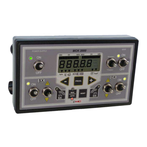
SOLID CONTROL MCK 2000 3.4 Front view Picture 9. Front view. The front panel allows the operator to display all the data of the working cycle. The following elements can be seen on the panel: REF. DESCRIPTION ON/OFF main switch for turning the Computer on and off (with green LED) “-“key for decreasing data to be set... -
Page 19: Keyboard
SOLID CONTROL MCK 2000 3.4.1 Keyboard FUNCTION ON and OFF switch. The switching on is indicated by the green LED MAIN bi-stable switch for opening and closing the sections: it works as a main switch for the left and right slit controls, for... - Page 20 SOLID CONTROL MCK 2000 FUNCTION Multifunction key: a quick pressure allows to select the value to be displayed. Keeping the key pressed for <3> seconds allows to reset the totalisers and reload the counter of the Kg left in the hopper.
- Page 21 SOLID CONTROL MCK 2000 FUNCTION Tri-stable switch allows to feed a third external motorised actuator connected to pins 8B and 8C of the connector, regardless of the status of the other inputs/outputs. Do not use this key if the machine is not equipped with motorised deflectors.
-
Page 22: Lcd Display
SOLID CONTROL MCK 2000 3.4.2 LCD Display REF. DESCRIPTION Display of left section target dose. Display of right section target dose. Display of instant dose distribution Total kg distributed. Feed-rate: Inductive sensor Radar sensor or impulsive GPS Partial processed area (independent totaliser) -
Page 23: Back View
SOLID CONTROL MCK 2000 3.5 Back view The following elements are present on the rear side of the Computer: Buzzer for the acoustic alarm; Connector for connection to wiring HARNESS; C. ID label; D. RS 232 connector, 9 poles, for connection to the printer (optional). -
Page 24: Accessories
SOLID CONTROL MCK 2000 4. Accessories 4.1 Standard accessories Table 4-1. Standard accessories CODE DESCRIPTION PF0481 Inductive sensor for speed D.18/5 with bracket PF0481 Inductive sensor for PTO rev/min CAV-0187 4 m wiring HARNESS (length is meant between main connector... -
Page 25: Programming
SOLID CONTROL MCK 2000 5. Programming 5.1 Programming of dose to be sprayed This programming phase can be accessed with the computer on, both in automatic or manual mode. Press the key briefly to display the programmed target value (it appears for a few seconds). -
Page 26: Programming Machine Parameters
SOLID CONTROL MCK 2000 PARAMETER PROGRAMMING (1). Working width in metres and cm Setting field step default :0.01 : 10.00 :0.1040.00 Hopper capacity expressed in Kg Setting field step default : 500 :09999 in relation to the type of processing, with simple or overlapped pass, the working width “L”... - Page 27 SOLID CONTROL MCK 2000 PARAMETER PROGRAMMING Number of pulses coming from the speed sensor for every 100 linear metres covered. Setting field step default : 200 : 50999 Impulses/revolution of the PTO: enter the number of impulses received by the PTO sensor at each revolution of the PTO shaft.
- Page 28 SOLID CONTROL MCK 2000 PARAMETER PROGRAMMING Adjusting the fertilizer capacity: 1A,1b5A,5b These 10 parameters can be customized on the basis of the machine application and type of product to be distributed. The set value is taken from practical tests and has the following meaning: ...
- Page 29 SOLID CONTROL MCK 2000 PARAMETER PROGRAMMING Product reserve alarm threshold: If, during operation, the remaining kg in the tank (calculated by the Computer) are below the set quantity for this parameter, a buzzer and visual alarm are triggered ( N.B. This function is operating only if parameter “U” (see chapter “Operation”...
-
Page 30: Operation
SOLID CONTROL MCK 2000 6. Operation 6.1 Operation examples Switch on the Computer (switch ON, see Picture 9 - ref.<A> on page 18). The Computer will run a <1.5> second test by switching on all display segments and activating the buzzer. Then, total working hours will be displayed for <3> seconds, finally the concentration in Kg/Ha of the product being distributed (which will be “0”... - Page 31 SOLID CONTROL MCK 2000 Each time the key is pressed, the following values are displayed cyclically, in this sequence: total amount of product distributed, feed-rate, total and partial area (in hectares) covered, (the hectares are only counted when at least one side is open and there is feed-rate), PTO speed.
- Page 32 SOLID CONTROL MCK 2000 : the display shows the “U” parameter followed by a Confirm with number indicating the tank contents in Kg; during operation the Computer calculates the number of kg distributed and subtracts this amount from the original tank filling reading, giving the number of kg left (ref.
- Page 33 SOLID CONTROL MCK 2000 Kg distributed) simply by holding down the key for more than <3> seconds with the total to be zeroed out on the display. The same key can be used to reload totals with the Kg set on the “U”...
-
Page 34: Automatic Mode
SOLID CONTROL MCK 2000 6.2 Automatic mode The automatic operating mode can be selected with the key: the selected mode is highlighted by the switching on of the relative LED in the key. During product spreading, the dose to be distributed can be changed at any time using the relative programming phase. -
Page 35: Manual Mode
SOLID CONTROL MCK 2000 In automatic mode, the “field border” function is also active which, using the keys , allows to differentiate the distribution of the right and left sections (and vice-versa) in percentage terms (from 5 to 50% settable). -
Page 36: Practical Example For Calculating The "C" Parameter To Be Programmed
SOLID CONTROL MCK 2000 6.4 Practical example for calculating the “C” parameter to be programmed In the “C” parameter you have to program the number of impulses the proximity sensor has to send to the Computer every 100 linear meters the machine works. - Page 37 SOLID CONTROL MCK 2000 N° of wheel revolutions (e.g. 30 ) Starting Finish Distance covered (e.g. 60 metres) point point CONCLUSION 100 metres number of references Constant “C” = on the wheel Wheel circumference in meters Picture 11. Practical example for calculating the “C” parameter.
-
Page 38: Automatic Calibration Of The "C" Parameter
SOLID CONTROL MCK 2000 6.5 Automatic calibration of the “C” parameter The automatic calibration of the “C” parameter is carried out by covering an established distance of 100 meters and following the listed routine: access programming (see chapter “Programming” on page 25) and display parameter “C”;... -
Page 39: Self-Positioning To Reference Points
SOLID CONTROL MCK 2000 6.6 Self-positioning to reference points The computer uses 2 reference points for calculating correspondence between the opening of the slits and the distributed product; it is possible to ensure that the computer automatically places the actuators in the two reference points (at 30% and at 75% of the stem stroke);... - Page 40 SOLID CONTROL MCK 2000 When the LED of key switches off, on the display program the average value of the measured weights (it is advisable to add the two weights and divide by 2). Now go to parameter “1b” by pressing , to complete product 3 calibration at the 75% point.
-
Page 41: How To Check Speed Sensor Operation D.18 Code 481
SOLID CONTROL MCK 2000 6.7 How to check speed sensor operation D.18 code 481 Check the functioning of the proximity sensor as follows: Switch on the Computer (switch ON, see Picture 9 - ref.<A> on page 18); A quick pressure on the... -
Page 42: Maintenance
SOLID CONTROL MCK 2000 7. Maintenance This section gives instructions on how to carry out ordinary and extraordinary maintenance. Ordinary maintenance refers to those operations which must be carried out periodically. As they do not require specific skills, they can be carried out by the users (operators etc.). -
Page 43: How To Replace The Protection Fuse
SOLID CONTROL MCK 2000 7.1.1 How to replace the protection fuse The computer fuse is internal and self-restoring. If the display goes into protection, it is necessary to: Disconnect the power supply. Wait for the fuse to cool (about 30 sec.) Reconnect the power supply. -
Page 44: Operating Anomalies
SOLID CONTROL MCK 2000 8. Operating anomalies In the event of problems with functioning , carry out these simple controls to check if repairs are needed. If the problem still remains after carrying out the suggested controls, consult your local dealer or contact MC elettronica Technical Service. - Page 45 SOLID CONTROL MCK 2000 ANOMALY CAUSE REMEDY Parameters “C” or “L" See chapter “Programming” page 25 are not correctly programmed In AUTOMATICO PTO is not active Activate the PTO mode, sectors do not See below “PTO rotating PTO revolutions are not open speed remains at “0”.
-
Page 46: Technical Data
SOLID CONTROL MCK 2000 9. Technical data 9.1 SOLID CONTROL MCK 2000 Technical data Power supply voltage : from 10 to 16 Vdc current absorption (without : < 1 A actuators) Fuse : internal self-restoring Operating features Protection rating : IP 65... -
Page 47: Grain Level Sensor Code 1403
SOLID CONTROL MCK 2000 9.2.3 Grain level sensor code 1403 Power supply voltage : from 10 to 30 VDC Output signal : NPN - NO Max. operating frequency : 1000 Hz Working temperature : - 25°C / +70°C Max. intervention distance... -
Page 48: Memorandum Of Programmed Data
SOLID CONTROL MCK 2000 10. Memorandum of programmed data We recommend to fill in the table below with the general data of the Computer. With this information it will be easier to reset the Computer programming in the event this must be changed when using the equipment with different machines. - Page 49 SOLID CONTROL MCK 2000 CAUTION!! DO NOT WASH USING A POWER WASHER WITH PRESSURE JET WARNING: THIS PRODUCT CONTAINS TIN AND LEAD. IT MUST BE DISPOSED OF AT THE END OF ITS LIFE CYCLE AT THE DESIGNATED DISPOSAL FACILITIES DELIVERED DIRECTLY TO MC ELETTRONICA SRL (ITALY).
- Page 50 SOLID CONTROL MCK 2000 NOTES Installation and use...
- Page 51 SOLID CONTROL MCK 2000 NOTES Installation and use...
- Page 52 Electronic equipment for agriculture www.mcelettronica.it Printed in Italy...
Need help?
Do you have a question about the MCK 2000 and is the answer not in the manual?
Questions and answers