
Summary of Contents for Basler BE3-25A
- Page 1 INSTRUCTION MANUAL AUTO-SYNCHRONIZER Model: BE3-25A Part Number: 9 1661 00 100 Publication Number: 9 1661 00 990 Date: February, 1985 Revision H: June, 1999 Courtesy of NationalSwitchgear.com...
- Page 2 CONFIDENTIAL INFORMATION of Basler Electric Company, Highland, IL. It is loaned for confidential use. Subject to return on request and with the mutual understanding that it will not be used in any manner detrimental to the interests of Basler Electric Company.
-
Page 3: Table Of Contents
Table of Contents Paragraph Title Page SECTION 1 GENERAL INFORMATION 1-1 Description .......................1-1 General Description ..................1-1 Basic Unit Description................1-1 Frequency/Phase Angle Matching System ..........1-2 Voltage Matching Option ................1-2 Dead Bus Closing Option .................1-3 1-2 Specifications ....................1-3 1-3 Style Chart......................1-4 SECTION 2 THEORY OF OPERATION 2-1 System Theory of Operation................2-1 Basic Unit (Without Options) ..............2-1 Basic Unit (With Options) .................2-1... - Page 4 4-16 SSE and SER-CB Interconnection............4-8 4-17 SSR Interconnection................. 4-9 List of Tables Table Title Page Physical Specifications ................1-3 Electrical Specifications ................1-4 Controls.....................3-1 Indicators....................3-1 Jumpers ....................3-7 BE3-25A and Breaker Connections ............4-4 Troubleshooting Chart ................5-1 Replacement Parts ...................6-1 Courtesy of NationalSwitchgear.com...
-
Page 5: Section 1 General Information
Basic Unit Description. (1) The basic BE3-25A Auto-Synchronizer monitors both the oncoming generator and bus voltages then permits synchronizing the generator to an energized station bus or to another genera- tor when the following predetermined conditions are satisfied: (a) The frequency of the oncoming generator and the bus are matched to within ±0.1 Hertz. -
Page 6: Frequency/Phase Angle Matching System
(2) Two types of voltage matching are available: (a) "Bipolar" regulator correction signals for use with the summing point input of Basler Electric voltage regulators (types: SSR, SR, KR, and XR) and exciter regulators (types: SSE and SER-CB). -
Page 7: Dead Bus Closing Option
For output contacts, the contacts are closed until the conditions for acceptable breaker closure are attained. NOTE If the voltage regulator is not properly adjusted, the BE3-25A output may not be able to drive the regulator far enough to allow synchroni- zation. -
Page 8: Style Chart
The model number of the Synchronizer is a combination of letters and numbers indicating the features and options. Refer to Figure 1-1 for the style chart which shows the various options and features. Figure 1-1. BE3-25A Style Chart. Courtesy of NationalSwitchgear.com... -
Page 9: Section 2 Theory Of Operation
Basic Unit (With Options) System Theory of Operation. NOTE Even though the BE3-25A always has frequency matching, for pur- poses of discussion, it is considered an option because of the two types that may be selected (summing point or contacts). -
Page 10: Synchronizer Theory Of Operation
frequency (i.e.: the output for a 3 Hertz difference is larger than that for a 1 Hertz difference.) If the Reset jumper is installed to provide internal operation, the signals will continue being output until the phase angle is within the front panel setting. If the Reset function is being controlled externally, the correction signals will continue until the external reset contacts are closed. -
Page 11: Dead Bus Option
(2) The voltage correction signals will drive either a "raise/lower" contact type output for use with motor operated control (MOC) type voltage regulators or a "bipolar" type output for use with the summing point type input of Basler Electric voltage regulators (types SSR, XR, SR, and KR) and for exciter regulators (types SSE and SER-CB). -
Page 12: Synchronizer Block Diagram
Figure 2-2. Synchronizer Block Diagram. Courtesy of NationalSwitchgear.com... -
Page 13: Section 3 Controls, Indicators, & Jumpers
SECTION 3 CONTROLS, INDICATORS, & JUMPERS 3-1. CONTROLS The BE3-25A controls are shown in Figure 3-1 and are described in Table 3-1. NOTE Not all controls are on all styles. Table 3-1. Controls. CONTROL FUNCTION TEST/OPERATE Switch Selects either the TEST or the OPERATE Mode. -
Page 14: Controls, Indicators, And Jumpers
1 0 A A T 1 2 0 V A C O R 2 8 V D C S Y N C 7 . 5 A A T 2 2 0 V A C Basler Electric % V O L T Highland, Illinois... -
Page 15: Style A2N
R A T I N G S N C 10A AT 120 VAC OR 28 VDC S Y N C 7.5A AT 220 VAC Basler Electric % V O L T Highland, Illinois M A T C H T E S T O P E R A T E Figure 3-1A. -
Page 16: Style B1D
S N C D B 2 10A AT 120 VAC OR 28 VDC S Y N C 7.5A AT 220 VAC Basler Electric % V O L T Highland, Illinois M A T C H T E S T O P E R A T E Figure 3-1B. -
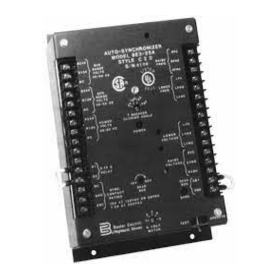
Page 17: Style C2D
S N C D B 2 10A AT 120 VAC OR 28 VDC S Y N C 7.5A AT 220 VAC Basler Electric % VOLT Highland, Illinois M A T C H TEST O P E R A T E Figure 3-1C. -
Page 18: Style W1D
1 0 A A T 1 2 0 V A C O R 2 8 V D C S Y N C 7.5A AT 220 VAC Basler Electric % V O L T Highland, Illinois M A T C H... -
Page 19: Jumpers
3-3. JUMPERS The BE3-25A jumpers are shown in Figure 3-1 and Figure 3-2 and are described in Table 3-3. NOTE Not all jumpers are required for all styles. Table 3-3. Jumpers. JUMPER FUNCTION RESET Jumper Used to enable the internal reset function. Refer to paragraph 1-1.b.3 and 2-1.b.1.a. -
Page 20: Installation
(216) NOTE: ALL DIMENSIONS ARE IN INCHES (MILLIMETERS). Figure 4-1. BE3-25A Outline Drawing . 4-2. INTERCONNECTION a. Power and Sensing Connections. Connect the power and sensing inputs to the BE3-25A as shown by Figures 4-2 through 4-5. Courtesy of NationalSwitchgear.com... -
Page 21: Power And Sensing Connection, 240 Vac, Power From Bus
Figure 4-2. Power and Sensing Connection, 240 Vac, Power From Bus. Figure 4-3. Power and Sensing Connection, 240 Vac, Power From Generator. Courtesy of NationalSwitchgear.com... -
Page 22: Power And Sensing Connection, 120 Vac, Power From Bus
B » E » 3 » - » 2 » 5 » A Figure 4-4. Power and Sensing Connection, 120 Vac, Power From Bus. Figure 4-5. Power and Sensing Connection, 120 Vac, Power From Generator. Courtesy of NationalSwitchgear.com... -
Page 23: Circuit Breaker (Sync) Connection
Circuit Breaker (SYNC) Connection. Connect the circuit breaker to the BE3-25A as given in Table 4-1. Table 4-1. BE3-25A and Breaker Connections. Breaker Input BE3-25A SYNC Output c. Voltage Regulator and/or Governor "Raise/Lower" Connections. Connect the "raise/lower" contact outputs as shown by Figure 4-6. -
Page 24: Barber Coleman Dyn1 Interconnection
Figure 4-7. Barber Coleman DYN1 Interconnection. Figure 4-8. Barber Coleman ILS Interconnection. Courtesy of NationalSwitchgear.com... -
Page 25: Woodward 2301 Interconnection
Figure 4-9. Woodward 2301 Interconnection. Figure 4-10. Woodward 1712-1724 Interconnection. Figure 4-11. Woodward 2301A Interconnection. Courtesy of NationalSwitchgear.com... -
Page 26: Summing Point Voltage Regulator Connection
Figure 4-12. AMBAC International CU673C Interconnection. e. Summing Point Voltage Regulator Connection. Connect the voltage regulator to the BE3- 25A as shown by Figures 4-13 through 4-17. Figure 4-13. KR, SR-F, SR-E, and SR-H Interconnection. Courtesy of NationalSwitchgear.com... -
Page 27: Sr4A And Sr8A Interconnection
Figure 4-14. SR4A and SR8A Interconnection. Figure 4-15. XR2001, XR2002, and XR2003 Interconnection. Figure 4-16. SSE and SER-CB Interconnection. Courtesy of NationalSwitchgear.com... -
Page 28: Operation
If the governor and the voltage regulator are not properly adjusted (refer to the individual governor and voltage regulator manuals), the BE3-25A may not be able to drive the governor or voltage regulator enough to allow synchronization. (All Models.) Set the front panel TEST/OPERATE switch to the TEST position. -
Page 29: Pre-Operational Check-Out
(Options A, B, or W Only.) Refer to Figure 3-2 and connect the Governor Stability Jumper for medium response time at terminals G1 and G2. (Options 1 or 2 Only.) Rotate the front panel % VOLT MATCH switch to select the desired voltage difference (1%, 2%, 3%, 4% or 5%) that is required for synchroniza- tion. -
Page 30: Section 5 Maintenance
SECTION 5 MAINTENANCE INSTRUCTIONS 5-1. PREVENTIVE MAINTE- NANCE A periodic inspection of the unit should be made to ensure that it is clean and free from accumulations of dust and moisture. Ensure that all wire con- nections are clean and secure. 5-2. - Page 31 Table 5-1. Troubleshooting Chart - Continued. MALFUNCTION TEST OR INSPECTION CORRECTIVE ACTION 3. No Voltage Regulator Control. Step 1. Check all wiring for proper connections. If wiring is not proper, reconnect wiring. If wiring is proper, proceed to step 2. Step 2.
- Page 32 Table 5-1. Troubleshooting Chart - Continued. MALFUNCTION TEST OR INSPECTION CORRECTIVE ACTION 5. SYNC Indicator Does Not Illuminate. Step 1. Check all sync connections and wiring for proper connections. If wiring is not proper, reconnect wiring. If wiring is proper, proceed to step 2. Step 2.
-
Page 33: General
Refer to the appropriate manual for replacement parts information. When ordering parts from Basler Electric Company, be sure to specify the sys- tem number (9 1661 00 100), reference, Basler part number, quantity, and description.
Need help?
Do you have a question about the BE3-25A and is the answer not in the manual?
Questions and answers