Table of Contents
Advertisement
Quick Links
Advertisement
Table of Contents

Subscribe to Our Youtube Channel
Related Manuals for Daitsu FDHD-V-AC MOTOR Series

Summary of Contents for Daitsu FDHD-V-AC MOTOR Series
- Page 1 INSTALLATION AND MAINTENANCE MANUAL HIGH PRESSURE DUCT FDHD Serie FDHD-V/P - AC MOTOR Edition Models FDHD-18R-V FDHD-18R-P FDHD-24R-V FDHD-24R-P FDHD-30R-V FDHD-30R-P FDHD-36R-V FDHD-36R-P FDHD-48-V FDHD-48-P FDHD-60B-V FDHD-60B-P FDHD-75-V FDHD-75-P FDHD-100-V FDHD-100-P...
- Page 2 Page 1 of 48 INVESTING IN QUALITY, RELIABILITY & PERFORMANCE ISO 9001 QUALITY World Leading Design and Technology Every product is manufactured to meet Equipped with the latest air-conditioning test rooms the stringent requirements of the and manufacturing technology, we produce over internationally recognized ISO 9001 50,000 fan coil units each year, all conforming to the standard for quality assurance in design,...
-
Page 3: Table Of Contents
Page 2 of 48 Table of Contents A. Technical Data ................................... 5 A.1. General Description ................................5 A.2. General Specifications ................................ 6 A.2.1. 2-pipe Systems ................................6 A.2.2. 4-Pipe Systems................................7 A.3. Coil Data ..................................... 7 A.4. Sound Power Data ................................8 A.5. - Page 4 Page 3 of 48 D.15. Master-Slave Network ..............................33 D.15.1. Master Unit Control Settings ..........................33 D.15.2. Master Slave Network Setup ..........................34 D.15.3. Master Slave Communication Method ........................36 D.16. Open Modbus Protocol ..............................37 E. User Interface .................................. 40 E.1.
- Page 5 Page 4 of 48 Model Code Nomenclature FDHD Complete function onboard PCB with integrated group control functionality. Terminal strip only. Chilled/Hot Water, 4-Pipe Chilled/Hot Water, 2-Pipe Unit Sizes. 18-100 See General Specification section A for cooling and heating capacities High Static Hydronic Ducted Fan FDHD Coil SK2019 EU FDHD-V/P-AC-001...
-
Page 6: Technical Data
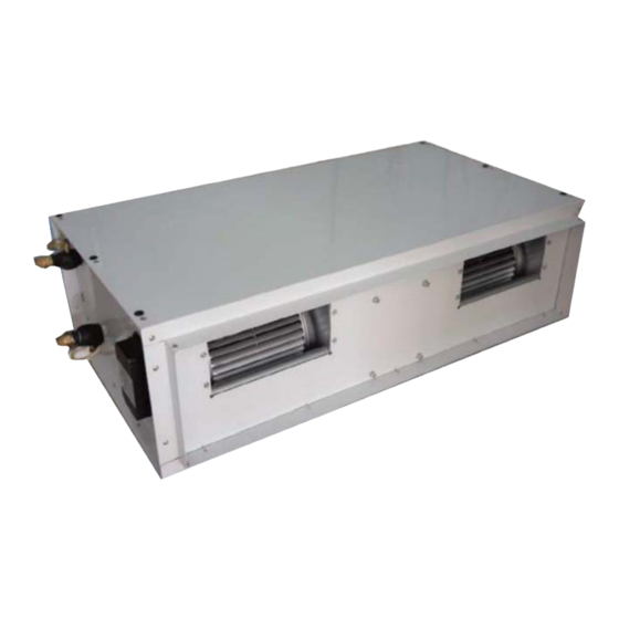
Page 5 of 48 Technical Data General Description The Duct Fan Coil is designed to meet and exceed the demanding requirements for efficiency and quiet operation. STRUCTURE Structure is made from electrostatic coating steel panels completed with couplings for the connection of ducting and gravity drain condensate pan with insulation. -
Page 7: General Specifications
Page 6 of 48 General Specifications A.2.1. 2-pipe Systems Product range: FDHD High Static Hydronic Ducted Fan Coil FDHD-V~ Hydronic Ducted 2-pipe Unit with AC motor FDHD-[Size]-V~ Configuration 2-pipe Number Of Fan Blowers Signal Twin Unit 230 / 1 / 50 Power Supply (V/Ph/Hz) Configuration 220 / 1 / 60... -
Page 8: 4-Pipe Systems
Page 7 of 48 A.2.2. 4-Pipe Systems Product range: FDHD High Static Hydronic Ducted Fan Coil FDHD-P~ High Static Hydronic Ducted Unit 4-pipe with 1-row Auxiliary Heating Coil and AC motor Non-standard configuration FDHD-[Size]-P~ 3.46 5.29 6.41 7.15 10.23 11.08 11.83 15.12 Heating... -
Page 9: Sound Power Data
Page 8 of 48 Sound Power Data Model FDHD-18R FDHD-24B FDHD-30R FDHD-36B speed Sound Power dB(A) 62.5 60.9 59.9 60.2 57.5 55.4 63.3 61.1 56.4 68.4 64.6 63.3 20.0 Hz 20.4 16.9 19.1 20.7 18.7 13.8 16.9 16.7 12.0 15.2 14.6 16.1 25.0 Hz... -
Page 10: Dimension Drawings
Page 9 of 48 Dimension Drawings Dimensions for FDHD-V (2-pipe) Model FDHD-18-V φ14 FDHD-24,30,36-V 1110 1042 1080 φ14 FDHD-48,60-V 1460 1392 1430 φ14 FDHD-75-V 1460 1392 1430 φ14 FDHD-100-V 1760 1692 1730 φ14 Model (Inch) FDHD-18-V 3/4" FDHD-24,30,36-V 3/4" FDHD-48,60-V 3/4"... - Page 11 Page 10 of 48 Dimensions for FDHD-P (4-pipe) Model FDHD-18-P φ14 FDHD-24,30,36-P 1110 1042 1080 φ14 FDHD-48,60-P 1460 1392 1430 φ14 FDHD-75-P 1460 1392 φ14 FDHD-100-P 1760 1692 1730 φ14 Model (Inch) FDHD-18-P 3/4" FDHD-24,30,36-P 3/4" FDHD-48,60-P 3/4" FDHD-75-P 1" FDHD-100-P 1"...
-
Page 12: Valve Information (Optional)
Page 11 of 48 Valve Information (Optional) A.6.1. On/Off Ball Valve Models Model Definitions 3-way ball valve with 3/4” connectors and on/ off motorized actuator 2-way ball valve with 3/4” connectors and on/ off motorized actuator 3-way ball valve with 1” connectors and on/ off motorized actuator 2-way ball valve with 1”... -
Page 13: Modulating Valve Models
Page 12 of 48 A.6.2. Modulating Valve Models Model Definitions 3/4" inch 2-way modulating valve and 24VAC actuator with 0-10VDC input 3/4" inch 3-way modulating valve and 24VAC actuator with 0-10VDC input 1" inch 2-way modulating valve and 24VAC actuator with 0-10VDC input 1"... -
Page 14: Installation
Page 13 of 48 Installation Safety Precautions • When installing, performing maintenance or servicing Polar Air fan coil units observe the precautions stated in this manual as well as those stated on the labels attached to the unit. • Ensure all local and national safety codes, laws, regulations, as well as general electrical and mechanical safety guidelines are followed for installation, maintenance and service. -
Page 15: Location
Page 14 of 48 Location Before installing and running the unit, please check the following: There must be enough space for unit installation and maintenance. Please refer to below figure for the unit's outlines and dimensions and for the minimum distance between the unit and the obstacle/ any obstructions/ its surroundings. Please ensure there is enough space for piping connections and electrical wiring. - Page 16 Page 15 of 48 >600mm >200mm DRAIN PIPE H1> *ESPmax/9.81 CEILLING H2>ESPmax/9.81 CAUTION Make sure the top of the unit is level after installation. The drain pan is designed with a slight gradient to facilitate drainage. CEILLING ACCESS PANEL WITH AIR RETRUN CAUTIONS Dimension M and N are determined by air duct design.
-
Page 17: Pipes Connection
Page 16 of 48 Pipes Connection Main Pipes Connection Check if the diameter of the water pipes is adequate for the actual length of the piping and not less than the diameter of the connection on the unit. When connecting the water pipes to the coil, do not damage the coil manifold. -
Page 18: Electrical Connection
Page 17 of 48 Electrical Connection Wiring connection must be done according to the wiring diagram on the unit. The unit must be GROUNDED well. An appropriate strain relief device must be used to attach the power wires to the terminal box. Field wiring must be complied with the national security regulations. - Page 19 Page 18 of 48 T2 Wiring Diagram for 24VAC Input Signal: 3-speed unit w ith E H W iring schem e IP A 18-D L-T24V -002 24Vac for thermostat 12Vac for thermostat C O M H eating signal (24V ac) C ooling valve signal(24V ac) O range (L) L-speed signal (24V ac)
-
Page 20: Maintenance
Page 19 of 48 Maintenance General Maintenance Installation and maintenance should be performed by qualified personnel who are familiar with local codes and regulations, and are also experienced with this type of appliance. Confirm that the unit has been switched OFF before installing or servicing the unit. A good general maintenance plan will prevent damage to and unexpected shutting down of the equipment. -
Page 21: Control Specifications: Complete Function Pcb: Ac-S1
Page 20 of 48 Control Specifications: Complete Function PCB: AC-S1 Abbreviations Ts = Setting temperature AUX1 = Hot water free contact Tr = Room air temperature AUX2 = Chilled water free contact Ti1 = Chilled water coil temperature MTV1 = Chilled water valve Ti2 = Hot water coil temperature MTV2 = Hot water valve I/O Port Definitions... -
Page 22: Wiring Diagram
Page 21 of 48 Wiring Diagram D.2.1. Complete Function PCB: AC-S1 AC-S1 Control Box Wiring scheme IPA19-DL-FDHD-AC-S Legend: DIPA-S1 SW1-5: set the unit address SW6: set unit type: master or slave Mode Configuration: SW7=0;SW8=0;unit operates in cooling/heating. EH2 EH1 PR2 PR1 FLOAT SW7=0;SW8=1;unit operates in cooling/heating with booster EH. -
Page 23: Configuration Settings
Page 22 of 48 Configuration Settings SK2019 EU FDHD-V/P-AC-001... -
Page 24: Fan Coil Unit On/Off
Page 23 of 48 D.3.1. Fan Coil Unit ON/OFF There are 3 ways to turn the system on or off: a) By the ON/OFF button on the remote handset or wired wall pad; b) By the programmable timer on the handset or wired wall pad. c) By the manual control button on fan coil unit. -
Page 25: Control Logics For 2-Pipe System
Page 24 of 48 Control Logics for 2-Pipe System D.4.1. With Valve Configuration COOL MODE a) MTV2, AUX1 and electric heater are always off. b) If Tr ≥ Ts + 1ºC (or + 4ºC if economy contact is activated), then cool operation is activated and MTV1 and AUX2 are turned on. - Page 26 Page 25 of 48 PRE-HEAT Pre-heat without electrical heater a) If Ti1 < 36ºC [or < 28ºC is selected by DIPB-S2 position SW4], then MTV1 and AUX1 are turned on, indoor fan remains off. b) If Ti1 ≥ 38ºC [or ≥ 30ºC is selected by DIPB-S2 position SW4], then MTV1 and AUX1 are turned on, indoor fan runs at set speed.
-
Page 27: Without Valve Configuration
Page 26 of 48 D.4.2. Without Valve Configuration COOL MODE a) Electric heater, AUX1, MTV1 and MTV2 are always off. b) If Tr ≥ Ts + 1ºC (or + 4ºC if economy contact is activated), then cool operation is activated and AUX2 is turned on. Indoor fan runs at set speed. -
Page 28: Control Logics For 4-Pipe System
Page 27 of 48 Control Logics for 4-Pipe System Note: 4-pipe system must always be equipped with 2 valves. COOL MODE a) MTV2, AUX1 and Electrical Heater are always off. b) If Tr ≥ Ts + 1ºC (or + 4ºC if economy contact is activated), then cool operation is activated, MTV1 and AUX2 are turned on. - Page 29 Page 28 of 48 PRE-HEAT Without Electrical Heater a) If Ti2 < 36ºC [or 28ºC depends on DIP setting], then MTV2 and AUX1 are on, then indoor fan remains off. b) If Ti2 ≥ 38ºC [or 30ºC depends on DIP setting], then MTV2 and AUX1 are on, then indoor fan runs at set speed. If indoor coil temperature sensor is damaged, then pre-heat time is set for 2 minutes and indoor fan runs at set speed.
-
Page 30: Sleep Mode
Page 29 of 48 Sleep Mode a) The sleep mode can only be set when the unit is in cool mode or heat mode. b) If the sleep mode is activated when the unit is in cool mode, then the indoor fan will run at low speed and Ts will increase by 2ºC over 2 hours. -
Page 31: Buzzer
Page 30 of 48 Buzzer If a command is received by the fan coil unit, the master unit will respond with 2 beeps for each setting, while the slave unit will respond with 1 beep. Auto Restart The system uses non-volatile memory to save the present operation parameters when system is turned off or in case of system failure or cessation of power supply. -
Page 32: Led Display And Error Description
Page 31 of 48 LED Display and Error Description LED receiver in ABS housing with 0.5m (SGS14HFCA-01010101) or 1.8m (SGS14HFCA-01010102) pre-wiring Complete Function PCB – S Type Control Fan speed setting LED Display Condition High speed Red LED On Normal Medium speed Yellow LED On Normal... -
Page 33: Led Display On Master/Slave Connection
Page 32 of 48 LED Display on Master/Slave Connection The error message indicating the defect status of all slave units will be shown in LED lights on the master unit. Master unit LED Unit No. Blink Remedy Unit 2 failure RED LED blinks 2 times, stops for 3s Check unit 2 communication plug and fix it Unit 3 failure... -
Page 34: Master-Slave Network
Page 33 of 48 Master-Slave Network The control PCB can be set either as a master unit or slave unit. Mater Unit Function a) The master unit sends data regarding its setting to the slave unit. b) The master unit settings are unit ON/OFF, Mode, Fan Speed, Timer, Clock, Set Temperature and Sleep Function for handset operation. -
Page 35: Master Slave Network Setup
Page 34 of 48 D.15.2. Master Slave Network Setup 1) Disconnect the communication plug from the control box 2) Communication plug A, B, A, B is printed on the main PCB. When you connect the wires, please ensure connection of A to A and B to B. 3) Connection wire i. - Page 36 Page 35 of 48 First unit Middle unit Last unit iii. Wire connection check a) After the wire connection is completed, please check if the wire colors are corresponded. b) Check the wire contact by using a multimeter. contact contact contact contact contact...
-
Page 37: Master Slave Communication Method
Page 36 of 48 D.15.3. Master Slave Communication Method There are two modes for the master-slave structure. Global Control communication The master unit will broadcast the settings to all slave units. During normal operation, slave units can receive commands from its wireless handset and wall pad control panel. Upon receiving the master global commands, all slave unit settings will be replaced by the master settings. -
Page 38: Open Modbus Protocol
Page 37 of 48 Open Modbus Protocol Transfer Mode: RTU, BAUD Rate: 9600bps, 8 data bit, 1 stop bit, None parity bit The communications require a delay of 80ms between reading an answer and sending the next command. All temperatures are equal to reading data*10 accuracy: 0.1 degree C. - Page 39 Page 38 of 48 Holding Register table: Description Address Type* Remark Cooling mode = 01(H) Humidify mode = 02(H) Mode setting 300000 Fan mode = 04(H) Heating mode = 08(H) Auto mode = 10(H) Low speed = 04(H) Medium speed = 02(H) Fan speed setting 300001 High speed = 01(H)
- Page 40 Page 39 of 48 Input Register table: Description Address Type* Remark Dip switch 1 status 400000 Dip switch 2 status 400001 Room temperature sensor 400002 Ti1 temperature sensor 400003 Ti2 temperature sensor 400004 Bit0 = Room temperature sensor error Bit1 = Ti1 temperature sensor error Bit2 = Ti2 temperature sensor error Bit3 = Float switch error Bit4 = Indoor coil low temperature protection...
-
Page 41: User Interface
Page 40 of 48 User Interface Remote Handset Interchange F and C on Display Press up and down buttons for 3 seconds, then release. Louver It is not available Swing It is not available Attention When unit with handset is the master unit, its settings are automatically sent to the slave units;... -
Page 42: Wired Wall Pad Controller
Page 41 of 48 Wired Wall Pad Controller Real Time display Day display Timer display Mode display Temperature display Fan speed display Master-Slave Button display Sleep icon Network Key lock SK2019 EU FDHD-V/P-AC-001... - Page 43 Page 42 of 48 1. Buttons function Button Name ONOFF MODE DOWN Function Switch on or off Switch between Change Fan Switch Modify Modify the unit modes Speed interfaces parameters parameters Press to change function setting: (CNT stands for pressing times) (1)...
- Page 44 Page 43 of 48 5. Temperature setting Press to set temperature. Set point temperature is shown on temperature display area. Press to confirm settings and exit. If no operation within 6 seconds, it will automatically exit and the setting will not be saved.
- Page 45 Page 44 of 48 12. Global control setting Press five times to set global control and “NETWORK” icon blinks. 1) Press , timer on/off icon blinks and all slave units’ timer on/off function setting are cancelled. 2) Press , all slave units time are set to the same as master units. Press , master unit sends commands to all online slave units.
-
Page 46: Sensor Resistance R-T Conversion Table
Page 45 of 48 Sensor Resistance R-T Conversion Table Resistance: R (25°C) = 10KΩ ± 1% Beta Constant: B (25/85) = 3977 ± 1% Rmin Rnom Rmax Rmin Rnom Rmax (°C) (KΩ) (KΩ) (KΩ) (°C) (KΩ) (KΩ) (KΩ) 182.7 191.8 26.11 26.9 27.71... -
Page 47: Troubleshooting
Page 46 of 48 Troubleshooting Symptoms Cause Remedy The fan coil does not - Check for presence of voltage No voltage start up - Check fuse on board Mains switch in the “OFF position - Place in the “ON” position Faulty room control - Check the room control Faulty fan... -
Page 48: Accessories
Page 47 of 48 Accessories TWO-WAY INTAKE PLENUM WITH DAMPER The two-way intake plenum with damper enables the room air intake duct and the external air intake duct to be connected when required. The cross section of the external air intake duct is accounted for 25% of the total cross section. SK2019 EU FDHD-V/P-AC-001... - Page 49 Page 48 of 48 DISCHARGE (AND INTAKE) PLENUM The discharge and intake plenum are supplied when the incoming or outgoing airflow must be directed to or from the bottom of the unit. It has a flange for connection to the basic unit or other accessories and blanked panels for optimum and flexible use.
- Page 50 Eurofred S.A. Marqués de Sentmenat 97 08029 Barcelona www.eurofred.es...
Need help?
Do you have a question about the FDHD-V-AC MOTOR Series and is the answer not in the manual?
Questions and answers