Table of Contents
Advertisement
Quick Links
Advertisement
Table of Contents

Related Manuals for Multitel SDTA-01

Summary of Contents for Multitel SDTA-01
- Page 1 SDTA-01 Step Down Transformer Adapter Version 2.1 User’s Manual...
- Page 3 User’s Manual PROPRIETARY INFORMATION The information contained in this document is the property of MULTITEL INC. Except as specifically authorized in writing by MULTITEL INC., the holder of this document shall: Keep all information contained herein confidential and shall protect same in whole or in part from disclosure and dissemination to all third parties and;...
-
Page 5: Table Of Contents
Table 2 – Wiring of the primary for 110 VCA ............. 11 Table 3 – Wiring of the primary for 220 VCA ............. 13 Table 4 – Wiring of the secondary circuit to the SDTA-01 ........14 Table 5 - Definition of J3 ................... 14 Table 6 - Definition of J8 ................... -
Page 6: Control Sheet
CONTROL SHEET ISSUE DATE DESCRIPTION ORIGINATOR 93/12/10 First English Issue P.P. 94/02/17 Corrections S. Vaughan 94/05/19 Certification update P. Poulin Technical and English review. Johanne Lavallée 01/07/30 Upgrade to a new format. 07/10/11 Changer adresse E. Boivin... -
Page 7: General Information
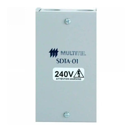
SDTA-01 1BGENERAL INFORMATION 1. GENERAL INFORMATION 1.1 Description The SDTA-01 is an interface accessory that converts AC voltage into AC voltage signal compatible with MULTITEL power monitoring systems (MPMS). Figure 1 - Physical appearance of the SDTA-01... -
Page 8: Content
Chapter 2, Specifications, contains the electrical, environmental and mechanical technical specifications for the SDTA-01. Chapter 3, Operation, describes the mode of operation and SDTA-01’s scale configuration. Chapter 4, Installation, provides the complete procedure for installing the SDAT-01. -
Page 9: Specifications
SDTA-01 2BSPECIFICATIONS 2. SPECIFICATIONS 2.1 Electrical Specifications Input voltage M-4181, 115 VAC max. M-4182, 230 VAC max. Current consumption 20 mA at 115 VAC 10.0 mA at 230 VAC Output signal 17 VAC at nominal input voltage (max. 28 VAC) 2.2 Environmental Specifications... -
Page 10: Operation
3BOPERATION 3. OPERATION 3.1 General The SDTA-01 is designed for interfacing alternative voltages from the line to MPMS such as Site Manager, MXP2 188 and Mirador. 3.2 Analog Channel Setup The MPMS' analog channel needs the proper scaling factor according to the AC voltage range (see following table). -
Page 11: Installation
4.2 Mounting the System The SDTA-01 is installed in an electrical room and as close as possible to the measurement AC voltage in order to minimise risk associated with the transmission of AC voltage. Install the SDTA-01 on any flat wall surface. Do not install the SDTA-01 in electrical box. -
Page 12: Cables And Connections
SDTA-01 4BINSTALLATION Figure 2 Wall installation of the SDTA-01 4.3 Cables and Connections This section provides the general installation procedures and demonstrates how to interconnect and put into service an SDTA-01. NOTE: you can find connectors J1 to J8 by locating their names on the board inside... -
Page 13: General Information
1. Remove the two screws holding the SDTA’s cover in place, using a screwdriver. 2. With a BX 14-2 cable, wire a 20A AC breaker maximum, coming from the electrical box to supply the SDTA-01. Table 2 – Wiring of the primary for 110 VCA... -
Page 14: Connecting The Primary To 220 Vac
SDTA-01 4BINSTALLATION Figure 3 Connecting 110 VCA to the SDTA-01 4.3.3 Connecting the Primary to 220 VAC Refer to Table 3 and Figure 4 for more detail. 1. Remove the two screws holding the SDTA’s cover in place, using a screwdriver. -
Page 15: Table 3 - Wiring Of The Primary For 220 Vca
SDTA-01 4BINSTALLATION Table 3 – Wiring of the primary for 220 VCA ELECTRICAL BOX BLACK BREAKER WHITE BREAKER AC2 (N) FRAME GROUND Linked by the cable’s metal shielding Figure 4 Connecting 220 VCA to the SDTA-01... -
Page 16: Connecting The Secondary Circuit
NOTE: use the cable conduit #3110 to keep the output cable away from the primary circuit. Pin 1 of J8 is linked to the positive analog channel of the MULTITEL power monitoring system and pin 2 of J8 is linked to the negative analog channel. Crimp for a MXP2 188 installation or screw directly into the Weidmuller connector for a Mirador or Site Manager installation. -
Page 17: Maintenance
5BMAINTENANCE 5. MAINTENANCE 5.1 Calibration The SDTA-01 does not need a periodic maintenance, however if the output values provided by the SDTA-01 are erratic (after verification), the MULTITEL power monitoring system’s may be programmed to compensate the differential in measurement. -
Page 18: Troubleshooting
When the problem is still not identified after reading this section, please refer to the Customer service centre. NOTE: before sending back any defective unit, please make arrangements with your nearest MULTITEL Customer service centre. - Page 19 The wiring is not according to specification in the SDTA-01 connector's definition. The SDTA-01 may be defective if all of the above possible causes are not true (refer to MULTITEL Customer service). The calibration is not adequate, refer to section 5.1 in this manual.
-
Page 20: Contacting Multitel
6. CONTACTING MULTITEL Our Customer service and Technical Support technicians are always eager to answer any question you might have about the SDTA-01. Simply telephone us, write to us or visit our Internet site where you will find FAQ’s for SDTA-01. -
Page 21: Index
· 16 Mechanical specifications · 7 MPMS · 8 Cables and connections · 10 MULTITEL, contacting · 18 connecting the primary to 110 VAC · 11 connecting the primary to 220 VAC · 12 connecting the secondary circuit · 14 definition of the connectors ·...
Need help?
Do you have a question about the SDTA-01 and is the answer not in the manual?
Questions and answers