Table of Contents
Advertisement
Quick Links
COSAMS Generic
User Manual
Commercial in Confidence
Analox Military Systems Ltd
15 Ellerbeck Court, Stokesley Business Park,
North Yorkshire, TS9 5PT, UK
T: +44 (0)1642 711400 F: +44 (0)1642 713900
W: www.analoxmilitarysystems.co.uk E: analoxams@analox.net
Copyright © 2015 Analox Ltd. All Rights Reserved.
Advertisement
Table of Contents

Subscribe to Our Youtube Channel
Related Manuals for ANALOX COSAMS Generic


Summary of Contents for ANALOX COSAMS Generic
- Page 1 User Manual Commercial in Confidence Analox Military Systems Ltd 15 Ellerbeck Court, Stokesley Business Park, North Yorkshire, TS9 5PT, UK T: +44 (0)1642 711400 F: +44 (0)1642 713900 W: www.analoxmilitarysystems.co.uk E: analoxams@analox.net Copyright © 2015 Analox Ltd. All Rights Reserved.
- Page 3 15/03/2016 Temperature specification updated 15/03/2016 29/10/2015 Original Issue - Derived from P0138-810-07 Document ref: P0138-840-03 April 2020 Page 3 of 89 Copyright © 2015 Analox Ltd. All Rights Reserved. Commercial in Confidence...
-
Page 4: Table Of Contents
Table of Contents Introduction ........................9 Modification state control ................... 10 System checklist ......................12 Transport and storage considerations ................ 13 Installation details ......................14 Overview ............................14 5.1.1 Tools/consumables required for installation ....................... 14 Mechanical installation ........................15 5.2.1 Mounting COSAMS ................................ - Page 5 Catalyst disposal ..........................75 Appendix A PremiOx Gold safety datasheet .............. 76 Appendix B Nanaucat safety data sheet ................ 81 Document ref: P0138-840-03 April 2020 Page 5 of 89 Copyright © 2015 Analox Ltd. All Rights Reserved. Commercial in Confidence...
- Page 6 COSAMS spare parts list ......................47 Table 11 Special maintenance equipment ....................47 Table 12 On board maintenance tasks ..................... 48 Document ref: P0138-840-03 April 2020 Page 6 of 89 Copyright © 2015 Analox Ltd. All Rights Reserved. Commercial in Confidence...
- Page 7 AVOIDED, COULD RESULT IN EQUIPMENT DAMAGE OR LOSS OF DATA. NOTE: THIS INDICATES INFORMATION THAT IS CONSIDERED IMPORTANT BUT IS NOT HAZARD RELATED. Document ref: P0138-840-03 April 2020 Page 7 of 89 Copyright © 2015 Analox Ltd. All Rights Reserved. Commercial in Confidence...
- Page 8 COSAMS Generic User Manual Int. Approved Safety information Please read this manual prior to installing and using the Analox COSAMS, paying particular attention to the following safety information: WARNING: DISCONNECT THE POWER SUPPLY BEFORE PERFORMING ANY MAINTENANCE WITHIN THE CABINET.
-
Page 9: Introduction
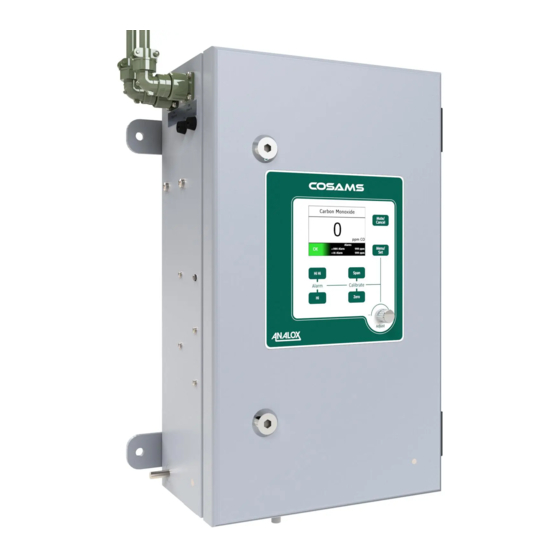
Int. Approved Introduction This manual details installation, operation and maintenance of the Analox COSAMS carbon monoxide (CO) sensor, developed for the submarine atmosphere monitoring system. Each COSAMS indicates the local CO concentration on a colour LCD and transmits a corresponding 4-20mA signal to the submarine’s Central Air Monitoring System. -
Page 10: Modification State Control
Modification Date authorised Details state First article delivery Table 1 Cabinet modification state Document ref: P0138-840-03 April 2020 Page 10 of 89 Copyright © 2015 Analox Ltd. All Rights Reserved. Commercial in Confidence... -
Page 11: Figure 2 Baseplate Modification State Label
Modification Date authorised/DCN Details state First article delivery Table 2 Baseplate modification state Document ref: P0138-840-03 April 2020 Page 11 of 89 Copyright © 2015 Analox Ltd. All Rights Reserved. Commercial in Confidence... -
Page 12: System Checklist
2m length of calibration sample tube USB lead COSAMS software CD User Manual Test Certificate/statement of Conformity Table 3 System checklist Document ref: P0138-840-03 April 2020 Page 12 of 89 Copyright © 2015 Analox Ltd. All Rights Reserved. Commercial in Confidence... -
Page 13: Transport And Storage Considerations
DETAILS OF PERMISSIBLE STORAGE TEMPERATURE, HUMIDITY AND PRESSURE RANGES CAN BE FOUND IN SECTION 15, ENVIRONMENTAL SPECIFICATIONS. NOTE: THE COSAMS WILL REQUIRE CALIBRATION AFTER TRANSPORT OR STORAGE. Document ref: P0138-840-03 April 2020 Page 13 of 89 Copyright © 2015 Analox Ltd. All Rights Reserved. Commercial in Confidence... -
Page 14: Installation Details
Installation of the hardware is possible using standard hand tools (i.e. spanners/socket set, screwdrivers, hex keys, soldering iron, etc.); no special tools or consumables are required. Document ref: P0138-840-03 April 2020 Page 14 of 89 Copyright © 2015 Analox Ltd. All Rights Reserved. Commercial in Confidence... -
Page 15: Mechanical Installation
(330 x 369mm centres) are indicated in Figure 5 Document ref: P0138-840-03 April 2020 Page 15 of 89 Copyright © 2015 Analox Ltd. All Rights Reserved. Commercial in Confidence... -
Page 16: Figure 5 Relative Positions Of Cosams Mounting Holes
COSAMS Generic User Manual Int. Approved Figure 5 Relative positions of COSAMS mounting holes Document ref: P0138-840-03 April 2020 Page 16 of 89 Copyright © 2015 Analox Ltd. All Rights Reserved. Commercial in Confidence... -
Page 17: Electrical Installation
A 3-way, female, chassis-mounted socket provides connection to the 4-20mA output signal and a mating connector (3-way, male, cable-mounting plug) is supplied with COSAMS. Document ref: P0138-840-03 April 2020 Page 17 of 89 Copyright © 2015 Analox Ltd. All Rights Reserved. Commercial in Confidence... -
Page 18: Ac Cable Identification
CONNECTOR. PIN 3 OF THE COSAMS CABINET-MOUNTED PLUG IS CONNECTED TO THE CABINET BODY IN ORDER TO MAKE PROTECTIVE EARTH CONNECTION DURING FACTORY SET UP AND TESTING. Document ref: P0138-840-03 April 2020 Page 18 of 89 Copyright © 2015 Analox Ltd. All Rights Reserved. Commercial in Confidence... -
Page 19: Dc Cable Identification
CONNECTOR. PIN 3 OF THE COSAMS CABINET-MOUNTED PLUG IS CONNECTED TO THE CABINET BODY IN ORDER TO MAKE PROTECTIVE EARTH CONNECTION DURING FACTORY SET UP AND TESTING. Document ref: P0138-840-03 April 2020 Page 19 of 89 Copyright © 2015 Analox Ltd. All Rights Reserved. Commercial in Confidence... -
Page 20: Signal Output
5.3.3 Signal output An Analox SDA output module controls a 4-20mA analogue signal proportional to the perceived CO concentration over the range 0-200ppm. The module is configured to operate in active mode and compliance is maintained for loop resistances up to 500Ω. -
Page 21: Technical Description
Gas exits the sensor’s optical bench and exhausts through the outlet on the right-hand-side of the COSAMS cabinet. Document ref: P0138-840-03 April 2020 Page 21 of 89 Copyright © 2015 Analox Ltd. All Rights Reserved. Commercial in Confidence... -
Page 22: Figure 7 Cosams Internal Electrical Arrangement (Ac Variant)
Figure 7 COSAMS internal electrical arrangement (AC variant) Document ref: P0138-840-03 April 2020 Page 22 of 89 Copyright © 2015 Analox Ltd. All Rights Reserved. Commercial in Confidence... -
Page 23: Figure 8 Cosams Internal Electrical Arrangement (Dc Variant))
COSAMS Generic User Manual Int. Approved Figure 8 COSAMS internal electrical arrangement (DC variant)) Document ref: P0138-840-03 April 2020 Page 23 of 89 Copyright © 2015 Analox Ltd. All Rights Reserved. Commercial in Confidence... -
Page 24: Power Supply
(which produces false-positive readings from electrochemical sensors) and has negligible cross-sensitivity to water vapour (unlike standard non-dispersive infra-red absorption sensors). Document ref: P0138-840-03 April 2020 Page 24 of 89 Copyright © 2015 Analox Ltd. All Rights Reserved. Commercial in Confidence... -
Page 25: 5S3 Control Interface
20mA output signal level (refer to Section 5.3.2 for details on the output signal). The Output Module’s Normally Open relay is energised to operate the COSAMS solenoid valve during the auto-zero operation. Document ref: P0138-840-03 April 2020 Page 25 of 89 Copyright © 2015 Analox Ltd. All Rights Reserved. Commercial in Confidence... -
Page 26: Electrical Schematic (Ac Variant)
Electrical schematic (AC variant) The internal wiring of the COSAMS is shown in Figure 9 Figure 9 Internal wiring schematic (AC variant) Document ref: P0138-840-03 April 2020 Page 26 of 89 Copyright © 2015 Analox Ltd. All Rights Reserved. Commercial in Confidence... -
Page 27: Electrical Schematic (Dc Variant)
The internal wiring of the COSAMS is shown in Figure 10 & Figure 11 Figure 10 Internal Wiring Schematic (Cabinet) (DC variant) Document ref: P0138-840-03 April 2020 Page 27 of 89 Copyright © 2015 Analox Ltd. All Rights Reserved. Commercial in Confidence... -
Page 28: Figure 11 Internal Wiring Schematic (Baseplate) (Dc Variant)
COSAMS Generic User Manual Int. Approved Figure 11 Internal Wiring Schematic (Baseplate) (DC variant) Document ref: P0138-840-03 April 2020 Page 28 of 89 Copyright © 2015 Analox Ltd. All Rights Reserved. Commercial in Confidence... -
Page 29: Operating Instructions
COSAMS Generic User Manual Operating instructions Controls Figure 12 shows the COSAMS front panel: Figure 12 COSAMS front panel Rotary encoder Mute/Cancel pushbutton Menu/Set pushbutton Alarm set point controls Calibration controls Start-up The COSAMS will automatically start up when power is supplied to it. Initially, the COSAMS will display a... -
Page 30: Warm-Up
If any alarm condition has been identified then the system status indicator will turn red and display the word ‘Alarm’. Document ref: P0138-840-03 April 2020 Page 30 of 89 Copyright © 2015 Analox Ltd. All Rights Reserved. Commercial in Confidence... -
Page 31: Menu
Access options to manage data log information Exit Exit from menu and return to normal operating screen Table 8 SDA operator console menu items Document ref: P0138-840-03 April 2020 Page 31 of 89 Copyright © 2015 Analox Ltd. All Rights Reserved. Commercial in Confidence... -
Page 32: Adjusting The Backlight
THE PRODUCT. FOR NEW SYSTEMS IT IS RECOMMENDED THAT THE BACKLIGHT IS SET TO AN INITIAL INTENSITY LEVEL OF 60% OR LESS TO MAXIMISE THE LIFESPAN OF THE DISPLAY. Document ref: P0138-840-03 April 2020 Page 32 of 89 Copyright © 2015 Analox Ltd. All Rights Reserved. Commercial in Confidence... -
Page 33: Auto-Zero Function
This screen shows the software version number, the instrument serial number, various settings, and the time until a service is due. Document ref: P0138-840-03 April 2020 Page 33 of 89 Copyright © 2015 Analox Ltd. All Rights Reserved. Commercial in Confidence... -
Page 34: Data Logging
2] Press the Menu/Set button again to select the ‘Data logging’ Menu option. 3] Press the Menu/Set button again to select ‘Delete all data-logs’. All logged data will be deleted. Document ref: P0138-840-03 April 2020 Page 34 of 89 Copyright © 2015 Analox Ltd. All Rights Reserved. Commercial in Confidence... - Page 35 COSAMS Generic User Manual Int. Approved To download logged data using the Data Download Tool (DDT) (Analox branded USB stick): 1] When using the Data Download Tool the files stored on the COSAMS device will not be affected. 2] Open the COSAMS enclosure using the supplied cabinet key 3] Locate the USB “TECH”...
- Page 36 6] This will automatically download the device datalogs, Once datalog download is complete the device will start downloading diagnosis logs 7] Once datalogs finish the fault log download will start. Document ref: P0138-840-03 April 2020 Page 36 of 89 Copyright © 2015 Analox Ltd. All Rights Reserved. Commercial in Confidence...
- Page 37 9] Once the USB device is removed, close the COSAMS cabinet door and lock. 10] The SOC will automatically reboot and enter a reduced COSAMS warm up period prior to normal operation mode. Document ref: P0138-840-03 April 2020 Page 37 of 89 Copyright © 2015 Analox Ltd. All Rights Reserved. Commercial in Confidence...
-
Page 38: Calibration
0 5] Press the Mute/Cancel button to clear any calibration messages that may remain on-screen. Document ref: P0138-840-03 April 2020 Page 38 of 89 Copyright © 2015 Analox Ltd. All Rights Reserved. Commercial in Confidence... -
Page 39: Performing A Span Calibration
0 below. 6] Press the Mute/Cancel button to clear any calibration messages that may remain on-screen. Figure 21 Span adjustment Document ref: P0138-840-03 April 2020 Page 39 of 89 Copyright © 2015 Analox Ltd. All Rights Reserved. Commercial in Confidence... -
Page 40: Alarms
CO concentration returns to a low level. Alarms are acknowledged by pressing the Mute / Cancel pushbutton. Document ref: P0138-840-03 April 2020 Page 40 of 89 Copyright © 2015 Analox Ltd. All Rights Reserved. Commercial in Confidence... -
Page 41: Clearing Alarms And Hysteresis
The hysteresis applied to an alarm is calculated as a percentage of the set point value with an upper limit imposed. Document ref: P0138-840-03 April 2020 Page 41 of 89 Copyright © 2015 Analox Ltd. All Rights Reserved. Commercial in Confidence... -
Page 42: Technical In-Service Support Software
The utilities on the CD are not required in normal use but may be of benefit in the event of in-service support being required. Document ref: P0138-840-03 April 2020 Page 42 of 89 Copyright © 2015 Analox Ltd. All Rights Reserved. Commercial in Confidence... -
Page 43: Troubleshooting
Table 9 shows a full list of fault messages together with a description of the cause and suggested remedies. Document ref: P0138-840-03 April 2020 Page 43 of 89 Copyright © 2015 Analox Ltd. All Rights Reserved. Commercial in Confidence... - Page 44 Analox. Sensor fatal error Interface has experienced a Should the interface PCB need to be fatal error. replaced, contact Analox. Document ref: P0138-840-03 April 2020 Page 44 of 89 Copyright © 2015 Analox Ltd. All Rights Reserved. Commercial in Confidence...
-
Page 45: Table 9 Fault Codes
Analox together with any information which may be relevant. Acknowledge the fault and attempt to continue operating. Table 9 Fault codes Document ref: P0138-840-03 April 2020 Page 45 of 89 Copyright © 2015 Analox Ltd. All Rights Reserved. Commercial in Confidence... -
Page 46: Maintenance
2321-0117 COSAMS membrane switch label P0138-407 Baseplate assembly including sensor Dependant on version COSAMS Data Download Tool (DDT) COSAMS DDT Document ref: P0138-840-03 April 2020 Page 46 of 89 Copyright © 2015 Analox Ltd. All Rights Reserved. Commercial in Confidence... -
Page 47: Special Maintenance Equipment
Analox recommend that a fairly small bottle is chosen, allowing the gas to be carried on board the submarine. For example, in the UK we would recommend the use of 110 litre S-Can bottles (360mm long x Ø86mm, 1.55 litres water capacity, fill pressure of 68 bar). -
Page 48: Periodic Maintenance
RECOMMEND THIS DOCUMENT IS USED TO TRACK ANY MAINTENANCE CARRIED OUT ON THE COSAMS. The Analox COSAMS has been designed to require minimal maintenance and minimal spare parts inventory. Most elements of the system maintenance can be carried out by Level 1 (on board maintenance personnel). -
Page 49: Figure 25 Cosams Internal Components (1)
Inlet pre-filter Solenoid valve COSAMS interface PCB Flow switch Auto-zero catalyst module SDA operator console Internal particulate filter Rotary encoder Document ref: P0138-840-03 April 2020 Page 49 of 89 Copyright © 2015 Analox Ltd. All Rights Reserved. Commercial in Confidence... -
Page 50: Figure 26 Cosams Internal Components (2)
Fuse holders (AC variant), fuse holders are located internally on DC variants Power filter Power supply unit (PSU) WARNING: DISCONNECT THE POWER SUPPLY BEFORE.PERFORMING ANY MAINTENANCE WITHIN THE CABINET. Document ref: P0138-840-03 April 2020 Page 50 of 89 Copyright © 2015 Analox Ltd. All Rights Reserved. Commercial in Confidence... -
Page 51: Filter Check And Replacement
3] Open the cartridge and remove the filter element: 4] Rotate the inlet end of the cartridge to the open (‘O’) position. Document ref: P0138-840-03 April 2020 Page 51 of 89 Copyright © 2015 Analox Ltd. All Rights Reserved. Commercial in Confidence... -
Page 52: Auto-Zero Catalyst Replacement
The breather may be removed from the cabinet by unscrewing the plastic nut on the rear. When installing a new breather, ensure that the O-ring is correctly seated in the groove on the back face of the breather. Document ref: P0138-840-03 April 2020 Page 52 of 89 Copyright © 2015 Analox Ltd. All Rights Reserved. Commercial in Confidence... -
Page 53: Removal And Replacement Of The Baseplate Assembly
5] Remove the four sets of M8 nuts/spring washers/flat washers that retain the baseplate. Document ref: P0138-840-03 April 2020 Page 53 of 89 Copyright © 2015 Analox Ltd. All Rights Reserved. Commercial in Confidence... - Page 54 12.3.4.1, in reverse order. CAUTION: ENSURE THE EARTH STRAP SITS ON THE MOUNTING STUD BEFORE REFITTING THE BASEPLATE. Document ref: P0138-840-03 April 2020 Page 54 of 89 Copyright © 2015 Analox Ltd. All Rights Reserved. Commercial in Confidence...
-
Page 55: Sample Pump Replacement
(Left spigot) and outlet (Right spigot). 9] Pop the mount clip open around the pump body. Document ref: P0138-840-03 April 2020 Page 55 of 89 Copyright © 2015 Analox Ltd. All Rights Reserved. Commercial in Confidence... - Page 56 (200mm blade length) PZ1 screwdriver, access is via the gap above the flow switch and below the GFC sensor. Document ref: P0138-840-03 April 2020 Page 56 of 89 Copyright © 2015 Analox Ltd. All Rights Reserved. Commercial in Confidence...
-
Page 57: Infra-Red Source Replacement
IR source harness. 3] Remove the two bolts and washers securing the source to the motor plate (requires a 2mm hex key). Document ref: P0138-840-03 April 2020 Page 57 of 89 Copyright © 2015 Analox Ltd. All Rights Reserved. Commercial in Confidence... - Page 58 VARIABILITY. CARE MUST BE TAKEN TO ENSURE THAT THE SOURCE HOUSING DOES NOT TOUCH THE SENSOR’S MOTOR AS THIS WILL CAUSE THE SENSOR TO MALFUNCTION. Document ref: P0138-840-03 April 2020 Page 58 of 89 Copyright © 2015 Analox Ltd. All Rights Reserved. Commercial in Confidence...
- Page 59 8] Once the COSAMS has been re-assembled, powered-up and the warm-up time has elapsed, calibrate the system (refer to section 12.4.8). Document ref: P0138-840-03 April 2020 Page 59 of 89 Copyright © 2015 Analox Ltd. All Rights Reserved. Commercial in Confidence...
-
Page 60: Non-Periodic Maintenance
3] Undo the M3 mounting hardware from the underside of the baseplate to remove the valve. 4] Recover the gas fittings from the base of the valve and install in the new valve. Document ref: P0138-840-03 April 2020 Page 60 of 89 Copyright © 2015 Analox Ltd. All Rights Reserved. Commercial in Confidence... -
Page 61: Flow Switch Replacement
Above: Flow switch pipework and mounting hardware Reverse steps [3] – [1] to install the new flow switch. Document ref: P0138-840-03 April 2020 Page 61 of 89 Copyright © 2015 Analox Ltd. All Rights Reserved. Commercial in Confidence... -
Page 62: Replacing The Power Supply Unit (Ac Variant)
PSU supporting brackets M3 x 16mm screws with M3 flat washers from the outside of the cabinet and secure with the following hardware internally: Document ref: P0138-840-03 April 2020 Page 62 of 89 Copyright © 2015 Analox Ltd. All Rights Reserved. Commercial in Confidence... - Page 63 (holds wires 1 & 2) M4 washer M3 washer M3 nyloc nut Bottom M3 nyloc nut 7] Fully tighten all hardware. Document ref: P0138-840-03 April 2020 Page 63 of 89 Copyright © 2015 Analox Ltd. All Rights Reserved. Commercial in Confidence...
-
Page 64: Replacing The Power Supply Unit (Dc Variant)
– they are all M3 x12 Pozi Pan Screws with M3 flat washers on the external face, secured with M3 flat washers & M3 Nyloc nuts on the internal face, secure the PSU in place. Document ref: P0138-840-03 April 2020 Page 64 of 89 Copyright © 2015 Analox Ltd. All Rights Reserved. Commercial in Confidence... -
Page 65: Replacing The Sda Output Module Pcb
4] Refit the PCB to the pillars and secure with the M2.5 Nylon washers and Nyloc Nuts. 5] Refit the electrical connectors. Document ref: P0138-840-03 April 2020 Page 65 of 89 Copyright © 2015 Analox Ltd. All Rights Reserved. Commercial in Confidence... -
Page 66: Replacing Sda Operator Console Membrane Label
7] Cut a small slot in the shield tag and fit over the stud on the rear top-right corner of the SDA with one of the Nord lock washers above and one below. Document ref: P0138-840-03 April 2020 Page 66 of 89 Copyright © 2015 Analox Ltd. All Rights Reserved. Commercial in Confidence... -
Page 67: Replacing The Sda Operator Console
4] Apply a bead of adhesive, e.g. silicone sealant, to the encoder/ribbon cable connector joint to prevent accidental detachment. Document ref: P0138-840-03 April 2020 Page 67 of 89 Copyright © 2015 Analox Ltd. All Rights Reserved. Commercial in Confidence... -
Page 68: Co Sensor Calibration
4] Leave the gas to flow for approximately 3 minutes and then measure the CO sensor output signal using the DVM across test points (Red +VE) and (Black -VE) on the baseplate. Document ref: P0138-840-03 April 2020 Page 68 of 89 Copyright © 2015 Analox Ltd. All Rights Reserved. Commercial in Confidence... - Page 69 CO in air span gas the output would be ~2.7 ± 0.05 V dc. 8] Repeat steps [2] through [6] until no further adjustment of the potentiometers is required. Document ref: P0138-840-03 April 2020 Page 69 of 89 Copyright © 2015 Analox Ltd. All Rights Reserved. Commercial in Confidence...
- Page 70 11] Allow the system temperature to stabilise for approximately 20 minutes and then perform a fine calibration, according to section 8. Document ref: P0138-840-03 April 2020 Page 70 of 89 Copyright © 2015 Analox Ltd. All Rights Reserved. Commercial in Confidence...
-
Page 71: Warranty
COSAMS Generic User Manual Int. Approved Warranty Document ref: P0138-840-03 April 2020 Page 71 of 89 Copyright © 2015 Analox Ltd. All Rights Reserved. Commercial in Confidence... -
Page 72: Fault Reporting To Analox
Fault reporting to Analox In the event of a fault arising, the following table may be of use when reporting the fault to Analox. Please complete whichever sections are believed to be relevant to the fault and return a copy to Analox - contact details can be found on the front page of this manual. -
Page 73: Specifications
40W (During normal operation) Fuse rating (F1, F2) 38x10mm, 16A anti-surge Signal output 4-20mA EMC compliance MIL-STD-461F ESD compliance EN 61000-4-2 Document ref: P0138-840-03 April 2020 Page 73 of 89 Copyright © 2015 Analox Ltd. All Rights Reserved. Commercial in Confidence... -
Page 74: Environmental Specifications
2 %vol H2 < 1ppm CO Cross sensitivity to carbon dioxide 5%vol CO2 < 1ppm CO Response time < 60s Document ref: P0138-840-03 April 2020 Page 74 of 89 Copyright © 2015 Analox Ltd. All Rights Reserved. Commercial in Confidence... -
Page 75: Disposal
Please check local regulations for information on the disposal of electronic products in your area. Analox will provide a disposal service if this is beneficial to the customer. Analox are registered for the disposal of WEEE in the UK through the Environment Agency (2013 Registration number WEE/KE0043SY). -
Page 76: Appendix A Premiox Gold Safety Datasheet
COSAMS Generic User Manual Int. Approved Document ref: P0138-840-03 April 2020 Page 76 of 89 Copyright © 2015 Analox Ltd. All Rights Reserved. Commercial in Confidence... - Page 77 COSAMS Generic User Manual Int. Approved Document ref: P0138-840-03 April 2020 Page 77 of 89 Copyright © 2015 Analox Ltd. All Rights Reserved. Commercial in Confidence...
- Page 78 COSAMS Generic User Manual Int. Approved Document ref: P0138-840-03 April 2020 Page 78 of 89 Copyright © 2015 Analox Ltd. All Rights Reserved. Commercial in Confidence...
- Page 79 COSAMS Generic User Manual Int. Approved Document ref: P0138-840-03 April 2020 Page 79 of 89 Copyright © 2015 Analox Ltd. All Rights Reserved. Commercial in Confidence...
- Page 80 COSAMS Generic User Manual Int. Approved Document ref: P0138-840-03 April 2020 Page 80 of 89 Copyright © 2015 Analox Ltd. All Rights Reserved. Commercial in Confidence...
-
Page 81: Appendix B Nanaucat Safety Data Sheet
COSAMS Generic User Manual Int. Approved Document ref: P0138-840-03 April 2020 Page 81 of 89 Copyright © 2015 Analox Ltd. All Rights Reserved. Commercial in Confidence... - Page 82 COSAMS Generic User Manual Int. Approved Document ref: P0138-840-03 April 2020 Page 82 of 89 Copyright © 2015 Analox Ltd. All Rights Reserved. Commercial in Confidence...
- Page 83 COSAMS Generic User Manual Int. Approved Document ref: P0138-840-03 April 2020 Page 83 of 89 Copyright © 2015 Analox Ltd. All Rights Reserved. Commercial in Confidence...
- Page 84 COSAMS Generic User Manual Int. Approved Document ref: P0138-840-03 April 2020 Page 84 of 89 Copyright © 2015 Analox Ltd. All Rights Reserved. Commercial in Confidence...
- Page 85 COSAMS Generic User Manual Int. Approved Document ref: P0138-840-03 April 2020 Page 85 of 89 Copyright © 2015 Analox Ltd. All Rights Reserved. Commercial in Confidence...
- Page 86 COSAMS Generic User Manual Int. Approved Document ref: P0138-840-03 April 2020 Page 86 of 89 Copyright © 2015 Analox Ltd. All Rights Reserved. Commercial in Confidence...
- Page 87 COSAMS Generic User Manual Int. Approved Document ref: P0138-840-03 April 2020 Page 87 of 89 Copyright © 2015 Analox Ltd. All Rights Reserved. Commercial in Confidence...
- Page 88 COSAMS Generic User Manual Int. Approved Document ref: P0138-840-03 April 2020 Page 88 of 89 Copyright © 2015 Analox Ltd. All Rights Reserved. Commercial in Confidence...
- Page 89 COSAMS Generic User Manual Int. Approved Document ref: P0138-840-03 April 2020 Page 89 of 89 Copyright © 2015 Analox Ltd. All Rights Reserved. Commercial in Confidence...
Need help?
Do you have a question about the COSAMS Generic and is the answer not in the manual?
Questions and answers