Table of Contents
Advertisement
Quick Links
CLOCKAUDIO CDT100 MK3
Dante Transporter
Clockaudio Ltd.
Unit C, Wellington Gate, Silverthorne Way,
Waterlooville, Hampshire PO7 7XY, UK
Tel: +44(0)23 9225-1193
Fax: +44(0)23 9225-1201
Email: info@clockaudio.co.uk
Clockaudio North America Inc.
2891 Rue du Meunier, Unit 103, Vaudreuil-Dorion,
QC, Canada J7V 8P2
Toll Free: 1-888-424-9797
Tel: 450-424-9797
Fax: 450-424-3660
Email: info@clockaudio.com
Clockaudio PTE Ltd.
BizTech Centre, Unit # 01-02, 627A Aljunied Road,
Singapore, 389842
Tel: +65 67484738
Fax: +65 67484428
Email: info@clockaudio.com.sg
1
Advertisement
Table of Contents

Summary of Contents for Clockaudio CDT100 MK3
- Page 1 CLOCKAUDIO CDT100 MK3 Dante Transporter Clockaudio Ltd. Unit C, Wellington Gate, Silverthorne Way, Waterlooville, Hampshire PO7 7XY, UK Tel: +44(0)23 9225-1193 Fax: +44(0)23 9225-1201 Email: info@clockaudio.co.uk Clockaudio North America Inc. 2891 Rue du Meunier, Unit 103, Vaudreuil-Dorion, QC, Canada J7V 8P2...
- Page 2 • Protect the power cord from being walked on or pinched particularly at plugs, convenience receptacles, and the point where they exit from the apparatus. • Only use attachments/accessories as specifi ed by Clockaudio. • Refer all servicing to qualifi ed service personnel. Servicing is required when...
- Page 3 LIMITED ONE YEAR WARRANTY The equipment is warranted for one year from date of purchase from Clockaudio against defects in materials or workmanship. This warranty does not cover equipment which has been abused or damaged by careless handling or shipping.
-
Page 4: Table Of Contents
DIAGRAM OF FUNCTIONS CONNECTING AUDIO SOURCES CONNECT TOUCH SWITCHES CONNECT TO A DANTE NETWORK CONNECT POWER TOUCH SWITCH PORT SETUP FRONT PANEL SWITCHES & DEMO/DIAGNOSTIC MODES FRONT PANEL LED INDICATOR CLOCKAUDIO CONTROL PANEL DIAGNOSTIC MODES MICROPHONE PLACEMENT MOUNTING API SPECIFICATION... -
Page 5: Getting Started
CDT-100 MK3 to be installed in close proximity to the microphones, minimizing interference-prone analog wiring. Up to 6 CDT100 MK3 units can be installed in a daisy chain configuration, further reducing the amount of cabling needed. -
Page 6: Feature Overview
• Compatible with any Dante or AES67 capable audio DSP or other Dante enabled device. • The CDT100 MK3 can be controlled and monitored with 3rd party control modules using direct UDP messages. Parameters that can controlled include: •... -
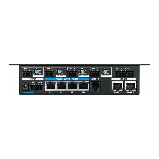
Page 7: Diagram Of Functions
6. OUTPUT TERMINAL BLOCKS Dante network audio outputs, assignable with Dante Controller 7. TOUCH SWITCH PORT RJ45 port for connection to Clockaudio Touch Switch controls 8. ARM-C PORT ARM-C port for connection to Clockaudio motorized microphone control 9. DANTE NETWORK PORTS... - Page 8 DEFAULT GAIN CDT100 MK3 PORT 1 PORT 2 10. POWER ON Power and CDT100 MK3 Status Indicator 11. TEST Activates diagnostic and demo modes 12. RESET Resets the test mode and restore defaults (see FRONT PANEL SWITCHES & DEMO/DIAGNOSTIC MODES section for detailed...
- Page 9 SETTING UP THE CDT100 MK3 We recommend setting up the CDT100 MK3 in the following order. Consult this User Guide for detailed information on each step. 1. Mount the CDT100 MK3 2. Connect audio sources 3. Connect Touch Switches and ARM Controller 4.
- Page 10 CONNECTION DIAGRAMS CONNECT UP TO 6 DEVICES TOTAL IN DAISY CHAIN CONFIGURATION CONNECTING MICROPHONES AND TS SWITCH CO12EN-RF BOUNDARY MICROPHONES TS005 UP TO 4 TOUCH SWITCHES TS-C1 CONNECTING ARM-C MOTORIZED MICROPHONES AND TS SWITCH ARM102N-RF MOTORIZED MICROPHONES + ARM-C MOTOR CONTROL RJ45 to ARM-C UP TO 4 TOUCH SWITCHES ARM-C MOTOR CONTROL...
-
Page 11: Connecting Audio Sources
CONNECTING AUDIO SOURCES The CDT100 MK3 has 4 microphone preamps designed to accept balanced microphones. Connect microphone(s) to the CDT100 MK3 with professional grade cabling. We recommend that the cable be shielded. FEMALE XLR JACK VIEW (front view) If using an XLR connector, wire the positive (pin 2) on the XLR to the first terminal. -
Page 12: Connect Touch Switches
The TS PORT allows users to connect a Touch Switch such as the TS 003 or TS 005 to the CDT100 MK3 for microphone muting and unmuting. Each TS Port can be connected to a single Touch Switch. Configure the functions of each switch with the Clock Audio CDT100 MK3 Windows Application. -
Page 13: Connect To A Dante Network
MK3 units directly to a switch in a non-daisy chain configuration), connect one of the CDT100 MK3 Dante Ports directly to an open port on a Dante network switch. The second Dante Port is used for Daisy Channing CDT100 MK3 networked... -
Page 14: Connect Power
1Gbit, off is 100 Mbit). DAISY CHAINING CDT100 MK3 UNITS A unique feature of the CDT100 MK3 is the ability to connect up to 6 units in a daisy chain configuration. Both power and network data can be daisy chained, resulting in decreased installation costs and simplified installs. - Page 15 * CDT-100 MK3 units only, no additional connected devices Additional power requirements must be considered when using Touch Switch ports with the CDT100 MK3. Each Touch Switch that is connected will increase power requirements. When using multiple units in a daisy chain configuration, please consider the total system power requirements.
- Page 16 DAISY CHAINING CDT100 MK3 UNITS DANTE PORTS CONNECT UP TO 6 DEVICES TOTAL IN DAISY CHAIN CONFIGURATION CO12EN-RF BOUNDARY MICROPHONES...
- Page 17 Confi gure the audio routing via the Dante Controller (available for Windows PCs and Mac OSX). Each CDT100 MK3 will appear on the Dante network with a unique name for identifi cation and routing. The default naming will be CDT100MK3-###### with the # replaced by the last six digits of the device’s MAC address.
-
Page 18: Touch Switch Port Setup
The TS PORT allows users to connect a Touch Switch such as the TS 003 or TS 005 to the CDT100 MK3. To test Touch Switch configuration, use the Clockaudio Control Panel application. Please consult the Clockaudio Control Panel manual for detailed instructions. -
Page 19: Front Panel Led Indicator
After a successful reset, power cycle the CDT100 MK3. If there was an issue resetting the CDT100 MK3 to the default values, the front panel LED will flash 8 quick red flashes. If you see 8 quick red LED flashes, try to reset the system again by holding the RESET for an additional... -
Page 20: Clockaudio Control Panel
IP address setup on the PC, however, communication with the CDT100 MK3 Windows application requires a compatible IP addresses. By default, the CDT100 MK3 will receive a dynamic IP address. If there is no DHCP server to assign an IP address, the device will self-assign an IP address. - Page 21 MICROPHONE SETUP The Channel Label section reflects the channel name used on the Dante network. When using multiple CDT100 MK3 units in a daisy chain configuration, it may be helpful to identify each microphone with a unique name. This can be done via the Dante Controller application from Audinate.
-
Page 22: Diagnostic Modes
Red: Signal at -3 dBFS or higher LATENCY Latency test mode measures how long it takes for a TS Port change message sent from the CDT100 MK3 to be received on an external controller. The application displays statistics about the number of messages sent/ received and the measured latency. -
Page 23: Microphone Placement
MICROPHONE PLACEMENT The CDT100 features a fixed input gain setting optimized for Clockaudio microphones. Follow these guidelines for best results: ONE CARDIOID MICROPHONE PER PERSON Place microphone 18” - 20” from the edge of the table ONE CARDIOID MICROPHONE FOR TWO PEOPLE... - Page 24 DUAL ELEMENT BOUNDARY MICROPHONE 72” maximum table width OMNI-DIRECTIONAL BOUNDARY MICROPHONE 48“ maximum table width For additional microphone placement recommendations, please contact the Clockaudio technical support department.
-
Page 25: Mounting
(front view) MOUNTING It is recommended that the CDT100 MK3 be secured to a flat surface with a CDT100 MK3 POWER TEST RESET screw through each mounting flange. Dimensions for mounting are shown in Figure 9 below. Use a No. 6 screw of a type and size that is applicable to the surface to which the CDT100 MK3 will be attached. - Page 26 The Dante interface unit shall be compatible with third party control systems for flexible control and monitoring in system applications. The Dante interface shall be compatible with all Clockaudio control devices. The Dante interface shall be compliant with the RoHS directive.
- Page 27 <0.005% at any gain, input signal 3dB below maximum Frequency Response 20Hz - 20kHz, +/- 1dB @ 40dB gain GENERAL SPECIFCATIONS TS Control Device Input RJ45, interfaces with Clockaudio TS-C1 and Clockaudio Touch Switches ARM-C Interface RJ12 Power Consumption 4 Watts nominal Max Product Dimensions 8.05”...
-
Page 28: Api Specification
API SPECIFICATION... - Page 29 1 UDP COMMAND SYNTAX The following commands are available for the CDT100 MK3. Commands are sent to UDP port 49494 on the target device. Responses are returned to the sending UDP port number. Please keep in mind that UDP is not a “guaranteed delivery” protocol, so it is possible for commands and responses to be occasionally lost.
- Page 30 Set TS Brightness STSB TS # (x) R=(10, 20, 30, 40, 50, 60, 70, x = 0 : All channels 80, 90, 100) x = [1...4] G=(10, 20, 30, 40, 50, 60, 70, 80, 90, 100) B=(10, 20, 30, 40, 50, 60, 70, 80, 90, 100) Get TS Brightness GTSB...
- Page 31 Get Latency Test Mode GLATENCY Measurements Set Control Port IP SETCTLNET (see description, below) (see description, below) Address Configuration GET Control Port IP GETCTLNET Address Configuration Set Audio Port IP SETAUDNET (see description, below) (see description, below) Address Configuration GET Audio Port IP GETAUDNET Address Configuration Reboot Device...
- Page 32 1.2 General Command Handling Commands are sent as ASCII character string with spaces used to delimit fields within a command. The entire command is terminated with a Carriage Return (0x0D). The device acknowledges a command by returning the command data with the string “ACK” inserted preceding the command data.
- Page 33 1.3.3 Load/Save The LOAD and SAVE commands allow different configurations to be saved into preset 0. When the CDT100 starts up preset 0 is used as the default configuration. A preset saves the CDT100 configuration, including the phantom power settings, the TS brightness settings and the ARM-C setting.
- Page 34 1.3.7 Set ARM-C State The Set ARM-C State command provides for activating or deactivating the ARM-C control signal. The following command activates the ARM-C control signal. SARMC 1<CR> Response ACK SARMC <CR> 1.3.8 Get ARM-C State The Get ARM-C State command provides to retrieving the current state of the ARM-C control signal.
- Page 35 1.3.9 Set Asynchronous IP Address The Set Asynchronous IP Address command is used to set the IP address and port number of the network node that asynchronous (unpolled) responses are sent to. Currently only the Switch Logic states from the four TS devices are reported. The following example command would setup the CDT100 to send message to port 12345 of node 192.168.50.4 when a switch changes state.
- Page 36 1.3.10 Firmware Update The Firmware Update command reboots the CDT100 into an update mode. The command has no parameters. FWUPDATE Response: None – the unit will immediately re-boot and the LED will change to yellow. 1.3.11 Boot Version The BVERSION command returns the current version of the Host MCU boot-loader firmware. The command has no parameters.
- Page 37 1.3.13 Get TS Status The Get TS status command is used to retrieve the logic input / output state of either all four ports or a selected port. The data is formatted similarly for each channel. CHxR=y provides the current state for channel x Red LED, y = 0 for inactive, 1 for active CHxG=y provides the current state for channel x Green LED, y = 0 for inactive, 1 for active...
- Page 38 1.3.14 Set TS Brightness The Set TS Brightness command provides for setting the brightness of the Red or Green LEDs on either all four TS ports, or a selected TS port. The brightness levels are implemented as a “duty cycle”. The duty cycle is set in 10% increments so valid values are 10, 20, 30, 40, 50, 60, 70, 80, 90 and 100.
- Page 39 1.3.16 Set RGB State The Set RGB State command provides for setting the brightness of the Red, Green and Blue LEDs in the TS(s). The following command sets the LEDs channel 1 to full on. SRGB 1 255 255 255<CR> Response: ACK SRGB 1 255 255 255<CR>...
- Page 40 1.3.19 Get Global Brightness Control The Get Global Brightness Control command returns the current setting of the global bright- ness control for each individual color. Each color can be set to a value between 0 (off) and 127 (max brightness) The following command gets the Global Brightness Control GGBC<CR>...
- Page 41 1.3.23 Set Output High-pass Filter The Set Output High-pass Filter command configures the high-pass filter (HPF) on the stereo output. The HPF can be turned off or set to a frequency between 50 and 150 Hz. The following command sets the Output HPF to 80 Hz: SOHPF 80<CR>...
- Page 42 This allows the response time of the associated network and control system to be measured. For this measurement to work, the following rules must be followed. • A control system must be present, and its IP address and port number must be config- ured with the SASIP command.
- Page 43 1.3.27 Set Control Port IP Address Configuration The Set Control Port IP Address Configuration command configures the IP address for the control port of the device. The IP address, subnet mask and gateway IP address can be configured. Dynamic addressing (DHCP or APIPA (Auto IP, 169.254.x.x)) can be selected by using addresses of all 0’s.
- Page 44 1.3.29 Set Audio Port IP Address Configuration The Set Audio Port IP Address Configuration command configures the IP address for the audio (Dante) port of the device. The IP address, subnet mask and gateway IP address can be configured. Dynamic addressing (DHCP or APIPA (Auto IP, 169.254.x.x)) can be selected by using addresses of all 0’s.
- Page 45 Response: ACK REBOOT<CR> Open-Source License Compliance The firmware in the CDT100 MK3 uses open-source software. To comply with the licens- ing requirement of this software, please note the following license information. lwIP TCP/IP Stack Copyright (c) 2001-2004 Swedish Institute of Computer Science. All rights reserved.
- Page 46 Unit C, Wellington Gate, Silverthorne Way, Waterlooville, Hampshire PO7 7XY, UK Tel: +44(0)23 9225-1193 Fax: +44(0)23 9225 1201 Email: info@Clockaudio.co.uk Clockaudio North America Inc. 2891 Rue du Meunier, Unit 103, Vaudreuil-Dorion, QC, Canada J7V 8P2 Toll Free: 1-888-424-9797 Tel: 450-424-9797 Fax: 450-424-3660 Email: info@clockaudio.com...
Need help?
Do you have a question about the CDT100 MK3 and is the answer not in the manual?
Questions and answers