Table of Contents
Advertisement
Quick Links
Advertisement
Table of Contents

Subscribe to Our Youtube Channel
Related Manuals for Rohde & Schwarz TSMA6-BP

Summary of Contents for Rohde & Schwarz TSMA6-BP
- Page 1 ® R&S TSMA6-BP Battery Pack Unit Getting Started (a0èN2) 4900903002 Version 06...
- Page 2 ® This manual describes the following R&S TSMA6 accessory: ● R&S ® TSMA6-BP Battery Pack Unit (4900.9001.02) ● R&S MNT ® ® BP89WH Batteries (1321.3772.00) for R&S TSMA6-BP © 2021 Rohde & Schwarz GmbH & Co. KG Mühldorfstr. 15, 81671 München, Germany...
-
Page 3: Table Of Contents
4.2 Connecting with External Power Supply.......... 12 4.3 Charging the Batteries............... 13 4.4 Connecting R&S TSMA6-BP with R&S TSMA6/6B......14 4.5 Connecting R&S TSMA6-BP with R&S TSME6 and R&S TSMExxDC ......................17 4.6 Connecting the R&S TSMA6-BP with Multiple Devices....19 4.7 Disconnecting the R&S TSMA6-BP from R&S TSMx Devices.. - Page 4 ® Contents R&S TSMA6-BP 6.2 Power On/Off..................30 6.2.1 Auto Power On..................30 6.2.2 Standby / Power On/Off................ 30 6.3 Battery Charging.................30 6.4 Automatic Power Path Switching............31 6.5 Monitoring Battery Charge State............31 6.5.1 Battery Charge Display................. 31 6.5.2 Rear Panel LEDs.................. 32 6.5.3 R&S TSMA6/6B web-GUI / Tray Icon (Only Host-Controlled Mode)..
-
Page 5: Safety Information
R&S TSMA6-BP Safety Information The product documentation helps you use the R&S TSMA6-BP safely and effi- ciently. Follow the instructions provided here and in the printed "Basic Safety Instructions". Keep the product documentation nearby and offer it to other users. -
Page 6: Documentation Overview
Getting Started Manual Introduces the R&S TSMA6-BP and describes how to set up and start working with the product. Includes basic operations, typical measurement examples, and general information, e.g. safety instructions, etc. A printed version is delivered with the instrument. - Page 7 ® Documentation Overview R&S TSMA6-BP Data Sheets and Brochures www.rohde-schwarz.com/brochure-datasheet/tsmx Getting Started 4900.9030.02 ─ 06...
-
Page 8: Key Features
Key Features R&S TSMA6-BP Key Features The R&S TSMA6-BP enhances the R&S TSMA6/6B device to a portable mea- surement solution based on a battery powered system. Key Features ● Power supply for R&S TSMA6/6B in portable applications ● Power supply for up to 4 additional devices (mobile network scanner R&S TSME6 resp. -
Page 9: Preparing For Use
® Preparing for Use R&S TSMA6-BP Unpacking the Instrument Preparing for Use Risk of injury and instrument damage The instrument must be used in an appropriate manner to prevent electric shock, fire, personal injury, or damage. ● Do not open the instrument casing. -
Page 10: Hardware
The batteries are premounted with max. 30% of charge. NOTE: Before first usage, the batteries must be fully charged in the R&S TSMA6-BP or with an external charger. ● Battery for R&S TSMA6-BP (R&S MNT_BP89WH, R&S No. 1321.3772.00) Getting Started 4900.9030.02 ─ 06... -
Page 11: Standard Accessory
Figure 4-1: R&S MNT-BP89WH 4.1.2 Standard Accessory The following items are included with shipment of the R&S TSMA6-BP: ● DC power cable with a cigarette lighter adapter ● 4 x collar screws M2.5 for connecting R&S TSMA6/6B resp. R&S TSME6 / TSMExxDC ●... -
Page 12: Connecting With External Power Supply
® Preparing for Use R&S TSMA6-BP Connecting with External Power Supply ● Collar screws (as a spare part) (R&S No. 4900.0804.00) To power TSMEx devices (scanner, downconverter), the following accessory cables are necessary. ● R&S TSMA6-BPPT (single TSMEx power cable, R&S No. 4900.1730.02) ●... -
Page 13: Charging The Batteries
TSME6 reps. R&S TSMExxDC). For charging the batteries, users have two possibilities: In-bay charging in the R&S TSMA6-BP Insert the batterie(s) in the correct way (charge indicator facing up). Take care of the nut in the battery and the pin inside the battery bay (see Chapter 6.6, "Battery... -
Page 14: Connecting R&S Tsma6-Bp With R&Stsma6/6B
Chapter 4.2, "Connecting with External Power Supply", on page 12). To connect the R&S TSMA6/6B with the R&S TSMA6-BP, the following steps must be performed. 1. Remove the cover cap from the docking connector of the R&S TSMA6/6B. Getting Started 4900.9030.02 ─ 06... - Page 15 Preparing for Use R&S TSMA6-BP Connecting R&S TSMA6-BP with R&S TSMA6/6B 2. Screw the collar screws on the top of the R&S TSMA6-BP with a Torx 8 screw driver. ● Torque: 0.66 Nm ± 0.05 Nm Figure 4-4: Collar screws 1 = Collar screws 3.
- Page 16 Preparing for Use R&S TSMA6-BP Connecting R&S TSMA6-BP with R&S TSMA6/6B Figure 4-5: Aligning R&S TSMA6-BP and R&S TSMA6/6B 1 = R&S TSMA6-BP 2 = Collar screws 3 = R&S TSMA6/6B 4 = Snap in holes on the bottom pane of R&S TSMA6/6B 4.
-
Page 17: Connecting R&S Tsma6-Bp With R&S Tsme6 And R&S Tsmexxdc
® Preparing for Use R&S TSMA6-BP Connecting R&S TSMA6-BP with R&S TSME6 and R&S TSMExxDC Figure 4-6: Connected R&S TSMA6B and R&S TSMA6-BP 1 = Attach R&S TSMA6/6B to R&S TSMA6-BP 2 = Move R&S TSMA6/6B to the rear side 3 = Power connection established (docking connector is snapped in) Connecting R&S TSMA6-BP with R&S TSME6... - Page 18 R&S TSMA6-BP Connecting R&S TSMA6-BP with R&S TSME6 and R&S TSMExxDC 1. Screw the collar screws (1) on the top of the R&S TSMA6-BP with a Torx 8 screw driver. ● Torque: 0.66 Nm ± 0.05 Nm 1 = Collar screws for connecting R&S TSME6 2 = Aux 1 / Aux 2 (auxiliary power out for connecting R&S TSME6/TSMExxDC via power...
-
Page 19: Connecting The R&S Tsma6-Bp With Multiple Devices
R&S TSME6 User Manual and the R&S TSMExxDC Getting Started. The R&S TSMA6-BP can be connected with several devices at the same time. In the following, examples for such multiple device combinations are shown. The connection of up to 4 R&S TSME6/TMSExxDC devices is possible. - Page 20 TSMA6-BP Connecting the R&S TSMA6-BP with Multiple Devices 4 collar screws are part of the standard accessory of the R&S TSMA6-BP. Additional collar screws are part of the R&S TSME6/TSMExxDC accessory or can be ordered as spare parts (R&S no. 4900.0804.00).
- Page 21 Additional collar screws are part of the R&S TSME6/TSMExxDC accessory or can be ordered as spare parts (R&S no. 4900.0804.00). 1. Screw the collar screws on the top of the R&S TSMA6-BP with a Torx 8 screw driver. ● Torque: 0.66 Nm ± 0.05 Nm...
- Page 22 1 = 8 x Collar screws (R&S No.4900.0804.00) 2. Align the collar screws with the snap-in holes on the bottom of the R&S TSME6 and R&S TSMExxDC and press these devices down. Figure 4-12: Aligning R&S TSMA6-BP, R&S TSME6 and R&S TSMExxDC Getting Started 4900.9030.02 ─ 06...
- Page 23 AUX1 / AUX2 to the DC IN socket of the devices (see Figure 4-13). Setup with TSMA6-BP + 2 x TSME6 + TSMExxDC Figure 4-13: TSMA6-BP + 2 x TSME6 + TSMExxDC To connect 3 and 4 R&S TSME6/TSMExxDC devices, proceed as follows.
- Page 24 R&S TSMA6-BP Connecting the R&S TSMA6-BP with Multiple Devices Figure 4-14: Aligning R&S TSMA6-BP, 2x R&S TSME6 and R&S TSMExxDC 1 = Collar screws 3. Align the collars with the snap-in holes on the bottom of the additional devices and press these devices down.
-
Page 25: Disconnecting The R&S Tsma6-Bp From R&Stsmx Devices
Figure 4-16: TSMA6-BP + TSMA6/6B + TSME6 + TSMExxDC Disconnecting the R&S TSMA6-BP from R&S TSMx Devices To disconnect the R&S TSMA6-BP and R&S TSMx devices (TSMA6/6B, TSME6, TSMExxDC), proceed as follows. 1. Power off all connected R&S TSMx devices. - Page 26 Preparing for Use R&S TSMA6-BP Disconnecting the R&S TSMA6-BP from R&S TSMx Devices 5. Only for R&S TSMA6/6B: Lift the release button (1) on both sides of the R&S TSMA6/6B and slide it in direction (2) until the device is released.
-
Page 27: Instrument Tour
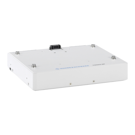
TSMA6-BP Rear Panel View Instrument Tour Front Panel View The front panel of the R&S TSMA6-BP does not provide any connectors or con- trol elements for operation. Figure 5-1: R&S TSMA6-BP - Front panel Rear Panel View The following figure provides an overview of the control elements and the connec- tors on the rear panel of the instrument. - Page 28 32. DC IN connector The DC IN connector is used to supply the R&S TSMA6-BP with DC power. A wide DC input range 11 V to 28 V is supported. Max. input current is 12 A. DC Output / Control R&S TSMA6/6B (docking connector) The docking connector is used for the power connection of a R&S TSMA6/6B...
-
Page 29: Operation
Operation Modes Operation For portable operation powered from the batteries, it is recommended to use the R&S TSMA6-BP always with 2 batteries in the bay. The batteries should have a comparable charging state as they are discharged simultaneously. ● Operation Modes.....................29... -
Page 30: Power On/Off
TSMA6/6B is provided. In standalone mode, there is no possibility to power off the output voltages of the R&S TSMA6-BP. To power on a R&S TSMA6-BP from standby mode again, following options are available: ● R&S TSMA6/6B connected: Press the power button the R&S TSMA6/6B. -
Page 31: Automatic Power Path Switching
Battery Charge Display Figure 6-1: R&S TSMA6-BP with R&S BP89WH batteries (R&S No.1321.3772.00) 1 = Charging state display (only for R&S TSMA6-BP and R&S BP89WH batteries) MNT-BP89WH: The discharge status is visible via the battery internal display without removing the batteries (see Figure 6-1). -
Page 32: Rear Panel Leds
Monitoring Battery Charge State 6.5.2 Rear Panel LEDs Figure 6-2: R&S TSMA6-BP - status LEDs 1 = Status LED for battery 1 2 = Status LED for battery 2 Table 6-1: LED states and their meaning (LED 1 and LED 2) in standalone mode (no R&S TSMA6/6B connected resp. -
Page 33: R&S Tsma6/6B Web-Gui / Tray Icon (Only Host-Controlled Mode)
® Operation R&S TSMA6-BP Battery Exchange - Hot Swapping Table 6-2: LED states and their meaning (LED 1 and LED 2) in host-controlled mode (R&S TSMA6/6B connected and switched on) Mode Color State Comment No battery Battery 1/2 not present... - Page 34 ® Operation R&S TSMA6-BP Battery Exchange - Hot Swapping The batteries are both discharged evenly. Therefore it is recommended to replace always both batteries. In case of a hot-swap, do not exchange the batteries simultaneously but one after the other.
- Page 35 Operation R&S TSMA6-BP Battery Exchange - Hot Swapping 4. Close the lid(s) until it clicks into place. NOTE: The R&S TSMA6-BP may be used only with closed battery lids. 5. Repeat step 1 step 4 for battery bay 2. Getting Started 4900.9030.02 ─ 06...
-
Page 36: Contacting Customer Support
® Contacting Customer Support R&S TSMA6-BP Contacting Customer Support Technical support – where and when you need it For quick, expert help with any Rohde & Schwarz product, contact our customer support center. A team of highly qualified engineers provides support and works with you to find a solution to your query on any aspect of the operation, program- ming or applications of Rohde &... -
Page 37: Index
® Index R&S TSMA6-BP Index Brochures ..........6 Customer support ........36 Data sheets ..........6 Getting started ........... 6 Hot swap ..........33 LED display ..........31 LED states host-controlled mode ......33 standalone mode ........ 32 Operation mode Standalone ..........29...
Need help?
Do you have a question about the TSMA6-BP and is the answer not in the manual?
Questions and answers