Table of Contents
Advertisement
Quick Links
Advertisement
Table of Contents

Summary of Contents for Veleon E-Motion
- Page 1 User Manual Service booklet...
-
Page 3: Table Of Contents
Table of Content Introduction ............................. 1 Veleon and its components ..................... 2 Getting started ..........................3 Advice for the driver ........................6 Designated usage ........................6 Checking screws and steering mechanism ................6 Regulatory requirements ......................6 Using a children’s bicycle seat ....................6 Intense usage ........................... - Page 4 Fastening torque for bolted connections ................18 Separating the frame and the front end ................18 Seat clamp/Quick releases ..................... 20 Adjusting the gear shift ......................21 Adjusting the brakes ......................21 Adjusting the mechanical brakes .................. 21 Adjusting the hydraulic disc brakes ................21 Adjusting the steering ......................
- Page 5 11 Maintenance and repair ........................ 67 Maintenance interval ......................67 Troubleshooting and fault clearance ..................67 The drive system does not start up ................67 Maintenance log ........................69 Inspection documentation ..................... 72...
-
Page 7: Introduction
Please always consider the road traffic regulations and ride with foresight and consideration, as not to endanger yourself or others. The Adomeit Group GmbH wishes you a great time with your Veleon and a safe journey at all times. -
Page 8: Veleon And Its Components
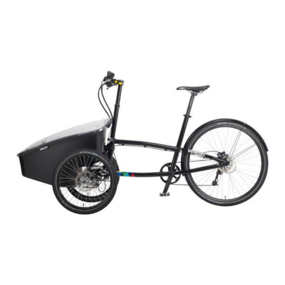
Introduction Veleon and its components stem Lockout (suspension) bell handlebar quick release skewers Front brake tires wheel chain guard inner bearing crankset pedals chain rear derailleur mudguard saddle rear brake... -
Page 9: Getting Started
Should the Veleon be delivered assembled, the following assembly steps can be skipped. You should only pay attention to possible transport damage and check the tire pressure. Before your first ride, take Veleon out of the package, check for completeness and assemble correctly. The following parts must be enclosed. - Page 10 Getting started Front end: 1. Unscrew the brake caliper incl. adapter from steering knuckle. 2. Mount the mudguards • The mudguard bracket is to be attached to the steering knuckle with two screws. The additional arm (riveted to mudguard) is fixed with the rear bolt of the brake caliper adapter.
- Page 11 Getting started Figure 2-2: Rear derailleur on the hanger Figure 2-3: Correct fixed quick release How to mount the cargo-box is described in chapter 8.3.1.2.
-
Page 12: Advice For The Driver
3 Advice for the driver Designated usage Veleon is a tilting trike for the urban environment. It is designed to ride on paved roads and dirt roads. We explicitly advice you that Veleon is not designed to ride over trackless terrain. Such improper use can lead to serious damage of the vehicle. -
Page 13: Intense Usage
Advice for the driver Intense usage Like all mechanical components, Veleon is exposed to heavy stress and thus is subject to wear and tear. Different materials and components can react differently to the exposure regarding wear and tiredness. If the life span of a component is exceeded, the part can fail suddenly and lead to serious injuries. -
Page 14: Establishing Readiness To Travel
Establishing readiness to travel 4 Establishing readiness to travel Checking the connection between frame and front end Frame and front end are connected with quick release skewers. Their position must be checked prior to every ride. The rear part must be positioned so that it forms a right angle to the front axle (Figure 4-1). The height of the frame must be adjusted so that the lower jaws occupy the free space provided in the front (figure 4-2 and 4-3). - Page 15 Establishing readiness to travel ADVICE The correct positioning of the front end is crucial for the drivability of Veleon. You should therefore check the correct positioning prior to every ride. Figure 4-4: Position of the connecting bolt The connecting bolts (1) should be checked for correct positioning prior to every ride. Incorrectly positioned and/or loose bolts can be dangerous.
-
Page 16: Checking And Adjusting The Saddle
Establishing readiness to travel Checking and adjusting the saddle Checking the saddle height One pedal has to be at the lowest point. Sit down on the saddle and place your heel on the pedal. If you sit upright on the saddle and your knee is straight, the saddle has the right height. Adjusting the saddle height, saddle tilt and saddle position This formula shows, at what height the saddle should be pre-positioned: 0,885 x inseam... -
Page 17: Checking And Adjusting The Handlebar
Checking and adjusting the handlebar Checking the handlebar height The height of the handlebar is not adjustable. Optionally, Veleon can be equipped with an adjustable handlebar riser. This enables the handlebar height to be adjusted toolless up to 100 mm. -
Page 18: Checking The Brakes
Establishing readiness to travel Checking the brakes Assignment of the brakes The right brake lever controls the rear wheel brake. The left brake lever controls the front wheel brakes Lock function of the front brake Figure 4-8: Brake lever in free position Figure 4-9: Brake lever in brake position If you want to use the lock function of the front brake, pull the brake lever and move the small crank (1) to the left. -
Page 19: Use The Lockout For Suspension (If Available)
Establishing readiness to travel Use the lockout for suspension (if available) The lever shown in Figure 4-10 triggers the lockout for the suspension. If the larger lever (1) is pushed forward, the damper is set much harder. In this way the damper compresses a lot less at the same pressure. -
Page 20: Checking The Tilt Lock
Figure 4-11: Grip shift lever for the tilt lock In position 2, the tilting of the Veleon is limited to 10 °. This setting can be used for acclimatization and for slow rides. We recommend position 1 with 30 ° tilting for complete maneuverability and cycling dynamics. -
Page 21: Checking The Toe Angle
Checking the steering system If Veleon has a rod steering, it doesn’t usually require a correction and this chapter can be skipped. Apart from checking the toe angle as described prior, it is very important to regularly check the tension of the steering cable. - Page 22 The steering cable, even single braids, may not show any signs of damage. If a damage of the steering cable (broken braids) is visible, the cable must be replaced immediately. Let exchange the cable by a specialist, e.g., the bike shop where you bought the Veleon. Pay attention to the service manual of the steering system.
-
Page 23: Useful Tips
Allowed maximum weight The allowed maximum weight of the Veleon is 200 kg (including the driver). The Veleon itself weighs between 21,5 and 46 kg, depending on the version. For optimum handling, it must be ensured that the Veleon is evenly loaded when you transport high loads. -
Page 24: Adjusting Veleon
Fastening torque [Nm] Table 1: valid for stainless steel screws A2-70 Separating the frame and the front end One of the distinctive features of Veleon is the possibility to separate the frame from the front end in a few easy steps. •... - Page 25 Remove the belt (2) • Detach the front end from the frame (Figure 6-4) To reassemble Veleon, repeat the steps of Chap. 6.2 in reverse order. Please make sure that the rear frame is aligned perpendicular to the front axle! (see chap. 4.1)
-
Page 26: Seat Clamp/Quick Releases
Adjusting Veleon Seat clamp/Quick releases Figure 6-6: Seat clamp closed Figure 6-5: Seat clamp open To achieve the correct fastening torque for the seat clamp (1), tighten the screw (2) by hand while the clamp is open (Figure 6-5). You know the correct clamping force when your force by hand remain to close the clamp (Figure 6-6). -
Page 27: Adjusting The Gear Shift
Adjusting Veleon Adjusting the gear shift Because of the complexity of adjusting the shift system, it is recommended that the shift system is only adjusted by a specialist. Adjusting the brakes Adjusting the mechanical brakes Figure 6-11: adjusting screws of the brakes The brakes can be adjusted by hand if the brakes are mechanical. -
Page 28: Adjusting The Steering
Adjusting Veleon New disc brakes need time to work correctly. During this time, you need more power to break. The same situation occurs when you changed the brake pads or/and the brake discs. Adjusting the steering Adjusting the cable steering (if available) To adjust the cable tension and toe angle, loosen the locknuts at first (4). -
Page 29: Adjusting The Rod Steering
Adjusting Veleon Adjusting the rod steering The toe angle is set correctly when the distance between the wheels at the front (a) is the same as the distance between the wheels at the rear (b). a = b If not, please correct the toe angle. -
Page 30: Adjusting The Damper (Remote Optional)
Adjusting Veleon Adjusting the damper (remote optional) The hardness can be adjusted via the air pressure in the damper. The damper can be pumped up to a pressure of about 15 bar. The hardness of the damper should be adjusted to the respective load. -
Page 31: Adjusting The Tilt Lock
Maintenance Adjusting the tilt lock The easiest way to adjust the tilt lock is to turn the adjusting screw (1) on the grip shift lever (Figure 6-22). This can be necessary when the tilt lock does not limit the tilting as usual. The adjusting should be done very carefully. -
Page 32: Maintenance
Maintenance 7 Maintenance It is recommended that Veleon is only serviced by a specialist. If the maintenance is done arbitrary, the risk of mistakes, and thus the danger while using Veleon, increases. In Chapter 11 “Maintenance and repair”, beginning with page 66, you will find how to maintain the Veleon. -
Page 33: Accessory And Replacement Parts
Attaching the cargo box The cargo box is connected to Veleon with three screws. Primary attaching points are two M8 and one M6 screw. Apart from that, the box is fastened with a tension belt. To attach the cargo box, put it onto the front end . - Page 34 Accessory and replacement parts Figure 8-1: Box with fastened screws Figure 8-2: Threads for attaching the cargo box Figure 8-3: Closing the tension belt Check the correct positioning of the cargo box and the functionality and correct usage of the safety elements before every ride.
-
Page 35: The Support Wheel
Accessory and replacement parts The support wheel Figure 8-4: Front end with cargo box Figure 8-5: Cargo box with support wheel The cargo box can be optionally equipped with a support wheel. The support wheel makes it possible to use the front end with the cargo box as trolley or stroller (Figure 8-4 and Figure 8-5). Separate the front end from the frame at first (see chapter 6.2). - Page 36 Accessory and replacement parts Figure 8-8: Quick release open Figure 8-9: Quick release closed To steer the transport or stroller easier, the steering must be blocked with the locking pin. The pin has to be inserted from the top into the silver fixation plate (Figure 8-10). Figure 8-10: Pin connects steering plate (black) with the fixing plate (silver) The pin must be pulled out after reassembling the front end and frame before continuing driving.
-
Page 37: Isofix Anchorage System
Safety seats that use the Isofix system can be attached to the anchorage system and are therefore safely attached to Veleon. In combination with the supporting wheel, Veleon can then be used as a stroller or a jogger. -
Page 38: Children's Seat Bench
Accessory and replacement parts Children’s seat bench The optional children’s seat bench was specially designed for Veleon and offers place for up to two children. To satisfy highest quality standards, we are using 5-point seatbelts that reliably prevent the child’s hip to move sideways. The seat bench is being attached to the Isofix-anchorage system of the cargo box. - Page 39 Accessory and replacement parts To attach the back of the seat bench, the tension belt has to be wrapped around the steering tube and fastened (Figure 8-19). In addition, carriage bolts and knurled nuts are used to attach the back rest to the cargo bike itself.
-
Page 40: Adjusting The Belt System
Accessory and replacement parts Adjusting the belt system The belt system can be easily adjusted for differently sized children. The grooves in the back rest are designed in a way that the belt shackle can be put through. Like this, the height of the belt system can be adjusted easily and quickly. -
Page 41: Shield
Accessory and replacement parts Shield The shield has two functions. On one hand it serves as a windshield for the children that are transported in the cargo box. On the other hand, the shield can be folded down to close the box. The shield can be additionally equipped with a lock to make the box lockable. -
Page 42: Rain Cover
Accessory and replacement parts Figure 8-26: Open quick release at spring Figure 8-25: Bending the springs The quick releases must be closed while cycling! Rain cover The shield can be extended to a complete rain protection with the rain cover. Beside the protection against rain, the rain cover is also a precaution against children getting their hands into the front wheels. - Page 43 Accessory and replacement parts Figure 8-28: Frame goes through tunnel Figure 8-27: Sidepieces mounted on frame If this is done, the frame can be inserted into the tube holders (Figure 8-29) that are placed at the back of the box. The sidepieces can then be attached to the shield and the box via press studs and Tenax- buttons (Figure 8-30).
- Page 44 Accessory and replacement parts Figure 8-29: Frame holder Figure 8-30: Mounted side panel Figure 8-31: To open pull the button Figure 8-32: Make sure that the arms are not bent If the frame is mounted and the sidepieces are attached to the box and shield, the headpiece can be mounted.
- Page 45 Accessory and replacement parts Figure 8-34: Tension belt for seat bench Figure 8-33: Headpiece Figure 8-35: Completely mounted rain cover Figure 8-36: Sideview rain cover If the seat bench is already mounted, release the tension belt for the headpiece to be mounted. After the headpiece is mounted, the tension belt can be put through the opening in the headpiece and re- fastened (Figure 8-34).
-
Page 46: Lighting
Lighting Veleon can be equipped with a dynamo hub (brand name SON). It will be installed in one of the front wheels. The rear light is mounted either on the fender or on the rack and is connected via cable with the headlight. -
Page 47: Ec-Declaration Of Conformity
EC machinery directive 2006/42/EEC as amended and the national laws and regulations adopting this directive. This declaration is no longer valid if the machine is modified without out our consent Description of machine (trade name): Veleon Brand/function/model/type: E-Motion Serial number/year of construction: LT12H00XXX/2016 Manufactures name or of his representative: Adomeit Group GmbH... -
Page 48: User Manual Of Heinzmann Directpower System
User manual of Heinzmann DirectPower System 10 User manual of Heinzmann DirectPower System The following operating instructions come directly from the manufacturer Heinzmann. The manufacturer is the sole author of this manual. The Adomeit Group GmbH assumes no liability for its content. The content of this manual is the sole responsibility of Heinzmann. - Page 49 User manual of Heinzmann DirectPower System...
- Page 50 User manual of Heinzmann DirectPower System...
- Page 51 User manual of Heinzmann DirectPower System...
- Page 52 User manual of Heinzmann DirectPower System...
- Page 53 User manual of Heinzmann DirectPower System...
- Page 54 User manual of Heinzmann DirectPower System...
- Page 55 User manual of Heinzmann DirectPower System...
- Page 56 User manual of Heinzmann DirectPower System...
- Page 57 User manual of Heinzmann DirectPower System...
- Page 58 User manual of Heinzmann DirectPower System...
- Page 59 User manual of Heinzmann DirectPower System...
- Page 60 User manual of Heinzmann DirectPower System...
- Page 61 User manual of Heinzmann DirectPower System...
- Page 62 User manual of Heinzmann DirectPower System...
- Page 63 User manual of Heinzmann DirectPower System...
- Page 64 User manual of Heinzmann DirectPower System...
- Page 65 User manual of Heinzmann DirectPower System...
- Page 66 User manual of Heinzmann DirectPower System...
- Page 67 User manual of Heinzmann DirectPower System...
- Page 68 User manual of Heinzmann DirectPower System...
- Page 69 User manual of Heinzmann DirectPower System...
- Page 70 User manual of Heinzmann DirectPower System...
- Page 71 User manual of Heinzmann DirectPower System...
- Page 72 User manual of Heinzmann DirectPower System...
-
Page 73: Maintenance And Repair
The complexity of the front axle requires proper maintenance and repair by trained specialists. The individual components of the Veleon have been carefully selected and matched to one other. Only original parts must be used for maintenance and repair. - Page 74 Maintenance and repair 3. If the display is switched on but there is no support from the motor, please remove the battery. a. Check all electrical contacts of the battery and of the controller and clean them with a soft and lint free cloth. b.
-
Page 75: Maintenance Log
The maintenance log serves as a guide for the workshop carrying out the individual maintenance work on the Veleon. Die inspections logs (from page 73) contain the same inspection steps and should be used for the written documentation of the individual maintenance work. - Page 76 Component Inspection Test Maintenance Rejection Measures of rejected Frame Rear frame Check for damage, damaged Shut off Veleon, new fractures, scratches frame Front frame Check for damage, damaged Shut off Veleon, new fractures, scratches front frame Clamping jaws Check for damage,...
- Page 77 Maintenance and repair Component Inspection Test Maintenance Rejection Measure if rejected Electric drive Display Check for damage Functional check damaged, Water reboot, install new inside display Control panel Functional check no reaction to button reboot, install new press display Cabling visual inspection System failure, Connect the plug...
-
Page 78: Inspection Documentation
Maintenance and repair Inspection documentation On the following pages you will find the sheets to document the maintenance. It is important to fill out this documentation and keep it as evidence. - Page 79 Maintenance and repair Customer Inspection Mileage Date 1./2./3./4./5./6./7./8./9./10. Component Inspection Test Maintenance Result Advice (ok, n.ok) Chassis Tires Check condition of Tire pressure check tires Brake fluid Check fluid level Brake pads/discs Check brake pads, brake discs Braking system Check fastening Functional check Parking brake Functional check...
- Page 80 Maintenance and repair Component Inspection Test Maintenance Result Advice (ok, n.ok) Drive/Gear shift Chain/Cassette/ Check for damage Pinion/Chainring Chain protection Check for damage Bottom Check fastening bracket/Crank Pedals Check fastening Gear shifter Check fastening Functional check Shift cable Check for damage Functional check Rear derailleur Check for damage...
- Page 81 Maintenance and repair Customer Inspection Mileage Date 1./2./3./4./5./6./7./8./9./10. Component Inspection Test Maintenance Result Advice (ok, n.ok) Chassis Tires Check condition of Tire pressure check tires Brake fluid Check fluid level Brake pads/discs Check brake pads, brake discs Braking system Check fastening Functional check Parking brake Functional check...
- Page 82 Maintenance and repair Component Inspection Test Maintenance Result Advice (ok, n.ok) Drive/Gear shift Chain/Cassette/ Check for damage Pinion/Chainring Chain protection Check for damage Bottom Check fastening bracket/Crank Pedals Check fastening Gear shifter Check fastening Functional check Shift cable Check for damage Functional check Rear derailleur Check for damage...
- Page 83 Maintenance and repair Customer Inspection Mileage Date 1./2./3./4./5./6./7./8./9./10. Component Inspection Test Maintenance Result Advice (ok, n.ok) Chassis Tires Check condition of Tire pressure check tires Brake fluid Check fluid level Brake pads/discs Check brake pads, brake discs Braking system Check fastening Functional check Parking brake Functional check...
- Page 84 Maintenance and repair Component Inspection Test Maintenance Result Advice (ok, n.ok) Drive/Gear shift Chain/Cassette/ Check for damage Pinion/Chainring Chain protection Check for damage Bottom Check fastening bracket/Crank Pedals Check fastening Gear shifter Check fastening Functional check Shift cable Check for damage Functional check Rear derailleur Check for damage...
- Page 85 Maintenance and repair Customer Inspection Mileage Date 1./2./3./4./5./6./7./8./9./10. Component Inspection Test Maintenance Result Advice (ok, n.ok) Chassis Tires Check condition of Tire pressure check tires Brake fluid Check fluid level Brake pads/discs Check brake pads, brake discs Braking system Check fastening Functional check Parking brake Functional check...
- Page 86 Maintenance and repair Component Inspection Test Maintenance Result Advice (ok, n.ok) Drive/Gear shift Chain/Cassette/ Check for damage Pinion/Chainring Chain protection Check for damage Bottom Check fastening bracket/Crank Pedals Check fastening Gear shifter Check fastening Functional check Shift cable Check for damage Functional check Rear derailleur Check for damage...
- Page 87 Maintenance and repair Customer Inspection Mileage Date 1./2./3./4./5./6./7./8./9./10. Component Inspection Test Maintenance Result Advice (ok, n.ok) Chassis Tires Check condition of Tire pressure check tires Brake fluid Check fluid level Brake pads/discs Check brake pads, brake discs Braking system Check fastening Functional check Parking brake Functional check...
- Page 88 Maintenance and repair Component Inspection Test Maintenance Result Advice (ok, n.ok) Drive/Gear shift Chain/Cassette/ Check for damage Pinion/Chainring Chain protection Check for damage Bottom Check fastening bracket/Crank Pedals Check fastening Gear shifter Check fastening Functional check Shift cable Check for damage Functional check Rear derailleur Check for damage...
- Page 89 Maintenance and repair Customer Inspection Mileage Date 1./2./3./4./5./6./7./8./9./10. Component Inspection Test Maintenance Result Advice (ok, n.ok) Chassis Tires Check condition of Tire pressure check tires Brake fluid Check fluid level Brake pads/discs Check brake pads, brake discs Braking system Check fastening Functional check Parking brake Functional check...
- Page 90 Maintenance and repair Component Inspection Test Maintenance Result Advice (ok, n.ok) Drive/Gear shift Chain/Cassette/ Check for damage Pinion/Chainring Chain protection Check for damage Bottom Check fastening bracket/Crank Pedals Check fastening Gear shifter Check fastening Functional check Shift cable Check for damage Functional check Rear derailleur Check for damage...
- Page 91 Maintenance and repair Customer Inspection Mileage Date 1./2./3./4./5./6./7./8./9./10. Component Inspection Test Maintenance Result Advice (ok, n.ok) Chassis Tires Check condition of Tire pressure check tires Brake fluid Check fluid level Brake pads/discs Check brake pads, brake discs Braking system Check fastening Functional check Parking brake Functional check...
- Page 92 Maintenance and repair Component Inspection Test Maintenance Result Advice (ok, n.ok) Drive/Gear shift Chain/Cassette/ Check for damage Pinion/Chainring Chain protection Check for damage Bottom Check fastening bracket/Crank Pedals Check fastening Gear shifter Check fastening Functional check Shift cable Check for damage Functional check Rear derailleur Check for damage...
- Page 93 Maintenance and repair Customer Inspection Mileage Date 1./2./3./4./5./6./7./8./9./10. Component Inspection Test Maintenance Result Advice (ok, n.ok) Chassis Tires Check condition of Tire pressure check tires Brake fluid Check fluid level Brake pads/discs Check brake pads, brake discs Braking system Check fastening Functional check Parking brake Functional check...
- Page 94 Maintenance and repair Component Inspection Test Maintenance Result Advice (ok, n.ok) Drive/Gear shift Chain/Cassette/ Check for damage Pinion/Chainring Chain protection Check for damage Bottom Check fastening bracket/Crank Pedals Check fastening Gear shifter Check fastening Functional check Shift cable Check for damage Functional check Rear derailleur Check for damage...
- Page 95 Maintenance and repair Customer Inspection Mileage Date 1./2./3./4./5./6./7./8./9./10. Component Inspection Test Maintenance Result Advice (ok, n.ok) Chassis Tires Check condition of Tire pressure check tires Brake fluid Check fluid level Brake pads/discs Check brake pads, brake discs Braking system Check fastening Functional check Parking brake Functional check...
- Page 96 Maintenance and repair Component Inspection Test Maintenance Result Advice (ok, n.ok) Drive/Gear shift Chain/Cassette/ Check for damage Pinion/Chainring Chain protection Check for damage Bottom Check fastening bracket/Crank Pedals Check fastening Gear shifter Check fastening Functional check Shift cable Check for damage Functional check Rear derailleur Check for damage...
- Page 97 Maintenance and repair Customer Inspection Mileage Date 1./2./3./4./5./6./7./8./9./10. Component Inspection Test Maintenance Result Advice (ok, n.ok) Chassis Tires Check condition of Tire pressure check tires Brake fluid Check fluid level Brake pads/discs Check brake pads, brake discs Braking system Check fastening Functional check Parking brake Functional check...
- Page 98 Maintenance and repair Component Inspection Test Maintenance Result Advice (ok, n.ok) Drive/Gear shift Chain/Cassette/ Check for damage Pinion/Chainring Chain protection Check for damage Bottom Check fastening bracket/Crank Pedals Check fastening Gear shifter Check fastening Functional check Shift cable Check for damage Functional check Rear derailleur Check for damage...