
Summary of Contents for joke ENESKApostpro
- Page 1 Operating manual ENESKApostpro Version 1.0 Order no: 0 210 000, 0 210 010, 0 210 003 and 0 210 012...
-
Page 2: Table Of Contents
ENESKApostpro with dry extraction......7 2.4.2 ENESKApostpro with oil extraction ......7 2.4.3 Optional FSX automatic fine dust measuring system . - Page 3 8.4.2 HT 60 D6, HT 60-D6 CNC ........25 8.4.3 JEHG 400 / JHG 210 .
- Page 4 17 Troubleshooting ........58 17.1 Problems with the unit controller........58 17.2 Problems with the ENESKAmicro motor controller.
-
Page 5: Notes On This Manual
Notes on this manual General information This operating manual enables users to operate, care for and maintain the ENESKApostpro post- processing system (referred to here as the “unit”). This operating manual is part of the unit and must always be kept available at the place of use. -
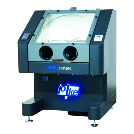
Page 6: Product Overview
Product overview Front view Fig. 1 Motor controller for handpieces Hood with handle Hand holes with gloves Unit controller 230 V socket Rear view Fig. 2 Rear door Dry compressed air port Main switch Mains plug Oily compressed air port... -
Page 7: Extraction System
2.4.2 ENESKApostpro with oil extraction The ENESKApostpro with oil extraction is used for work that produces reactive or very reactive dust. With oil extraction, the air that is sucked out of the working chamber is blown through the oil in the collector. The oil binds the dust and renders it inert. This prevents spontaneous ignition of the dust. -
Page 8: Nameplate
• ENESKApostpro with oil extraction or dry extraction system A comprehensive overview of the JOKE handpieces that can be connected to the unit can be found under ENESKAmicro in the section on drive systems and handpieces in the JOKE surface... -
Page 9: Technical Specifications
Technical specifications ENESKApostpro Supply voltage 400 V, 3-phase, 50 Hz Fuse rating of power supply 16 A slow blow Frequency 50 Hz Compressed air supply 5–6 bar, 1/2 inch Extraction performance 350 m³/h Power 3 kW Dimensions (W x H x D) 1300 x 1500 x 1790 mm Dimensions of working chamber 930 x 790 x 250–600 mm... -
Page 10: Approved Reduction Gears For Handpieces
Max. speed Handpiece Motor cable (rpm) - motor connection Micromotor JENK-250T 25,000 JENK-250T/EM Micromotor JENK-410S 40,000 JENK-410S/EM Micromotor JNK-261 NCL-261 Micromotor JNK-351 NCL-631 Marathon 3rd party motor 60,000 COMPACT SDE-BH60/EM Approved reduction gears for handpieces Max. speed Speed reduction Connection (rpm) JRG 01 30,000... -
Page 11: Safety
The unit is used for the final processing of additively manufactured components. Processing can refer to deburring, milling, grinding, polishing, removing residual powder and finishing of a workpiece. Only the following materials may be processed with the ENESKApostpro system: • Plastic • Steel •... -
Page 12: General Safety Instructions
• Never operate the unit without filter elements. • Only use the unit in technically perfect condition. • If dust escapes from the unit, switch off the unit immediately and contact JOKE customer service. • If live components are defective, switch off the unit immediately and have the defective com- ponents replaced by qualified personnel. -
Page 13: Controls And Indicators
Hand holes with gloves Door handles Hood with handle Door lock Foot pedal connection Height-adjustable feet Main switch 230 V socket Compressed air connection ENESKApostpro controller Mounting side depending on design. Compressed air connection (optionally with oil) Mounting side depending on design. 13 13... -
Page 14: Operating And Display Elements In The Working Chamber
5.2 Operating and display elements in the working chamber Fig. 5 Blower (two side blowers and one central) 6 Turntable (optional) FSX automatic fine dust measuring system Compressed air coupling socket G1/4" with integrated purge air unit (optional) KDG 14 NW7 Compressed air coupling socket G1/4"... -
Page 15: Elements Of The Control Panel
Elements of the control panel Fig. 7 Light intensity button Status message (plus = brighter) Height adjustment button (down) “Unit ON” button “Unit ready” symbol Height adjustment button (up) Optional display of current dust load (see Percentage display for lighting section 10) Shutdown cycle length display Light intensity button... -
Page 16: Operating And Display Elements In The Cabinet
Locking pin (2x) Shaker lever Sight glass (oil extraction only) Maintenance unit Lever for lowering collector (2x), with (May only be adjusted by JOKE Service) attachable double handle Mounting side depending on design. Oil drain cock (oil extraction only) Handle on collector... -
Page 17: Commissioning
Commissioning The unit is delivered fully assembled and brought to the kerbside by the haulage contractor. Transport Warning! Risk of crushing from heavy loads If the unit has to be transported, there is a risk that it may tip over. •... -
Page 18: Connecting The Power Supply
Connecting the power supply Danger! Risk of fatal electric shock If the unit is connected to an unsuitable power supply, there is a danger of electric shock. • Make sure the voltage, frequency and electrical protection of the mains supply match the specifications on the nameplate (see section 2.5). -
Page 19: Operation
Operation Switching on the power supply Fig. 13 Connecting the compressed air tool (if necessary) Fig. 14 Compressed air coupling socket G1/4" KDG Compressed air coupling socket G1/4" 14 NW7, compressed air with oil KDG 14 NW7 19 19... -
Page 20: Positioning The Workpiece
Positioning the workpiece Warning! Risk of injury from falling workpieces If heavy workpieces are transported incorrectly, they may fall down and cause serious injury. • Have heavy workpieces lifted into the working chamber by qualified personnel using suitable transport and lifting equipment. Warning! Risk of injury from workpieces tipping over If excessively heavy workpieces are placed in the working chamber, the unit may tip over and... -
Page 21: Logging In
Logging in 3 CLR < - ENTER 3. „adm“ + Enter 5. „8390“+ Enter Fig. 16 Starting the unit The unit can only be started when the hood is closed and no error messages are present. Fig. 17 » Press the “Unit ON” button (1). - While the unit is starting, the status message (2) “Unit started and door lock active”... -
Page 22: Checking The Direction Of Rotation Of The Side Duct Compressor
Checking the direction of rotation of the side duct compressor Fig. 18 Adjusting the lighting 3 CLR < - ENTER Fig. 19 The lighting can be adjusted by pressing the plus and minus buttons or by entering it using the keypad. -
Page 23: Operation With Eneskamicro Motor Controller
Operation with ENESKAmicro motor controller Connecting the motor cable to the unit Attention! Risk of damage to cables or sockets If cables are not correctly plugged into sockets, the sockets and cable may be damaged. • Always plug the motor cable carefully into the socket and make sure that the contacts and threads are not damaged. -
Page 24: Connecting A Handpiece
Connecting a handpiece Attention! Risk of damaging the motor or handpiece The motor and handpiece may be damaged if they are not correctly connected to each other. • Carefully push the motor and the handpiece into each other and make sure that the contacts, the motor shaft, the handpiece coupling and the threads are not damaged. -
Page 25: Compact Se, Ht 60, Ht 60 Small, Ht 60 Xl
8.4.1 Compact SE, HT 60, HT 60 SMALL, HT 60 XL CLICK CLICK Fig. 24 8.4.2 HT 60 D6, HT 60-D6 CNC Fig. 25 8.4.3 JEHG 400 / JHG 210 Fig. 26 25 25... -
Page 26: Jehr 500, Jir 310
8.4.4 JEHR 500, JIR 310 CLICK CLICK Fig. 27 8.4.5 JERA 270, JBMH 300 N Fig. 28 8.4.6 JERA 270 S Fig. 29 26 26... -
Page 27: Jih 300
8.4.7 JIH 300 90° 90° Fig. 30 8.4.8 JKC 345, JIC 390, JEKC 300, WE4-45, WE4-90 Fig. 31 8.4.9 JMFC 300 S / 300 M Fig. 32 27 27... -
Page 28: Setting The Language (If Necessary)
Setting the language (if necessary) The ENESKAmicro motor controller can only be operated if the device has been started, see section 7.5. Action Display = ESC = XXXXXXXX = = ESC = MAIN MENU = ----------------------------------- - __________ - __________ - __________ Open main menu = ESC = ___________ =... -
Page 29: Choosing A Motor
Choosing a motor Several motors can be connected to the control unit at the same time, but only one motor can be used at a time. The motor that was last connected to or used with the control unit is automatically selected. The motor button A, B or C belonging to this motor will flash. -
Page 30: Setting The Speed
Setting the speed Warning! Danger of injury from tools coming loose If tools are used at speeds for which they are not designed, they may come loose and cause injury. Damage to the handpiece is also possible. » Never exceed the maximum permitted speed of the connected components and accessories. Attention! Risk of damage to the handpiece when using long tools at high speeds If long tools are used at excessive speeds, the handpieces can be damaged. -
Page 31: Processing The Workpiece
Processing the workpiece As soon as a workpiece is processed, the extraction system switches on the side blowers. The central blower is always in operation as soon as the unit is started (see section 7.5). U/min Fig. 36 Danger! Danger of explosion due to sparks from processing workpieces! Despite the effective extraction of dust from the working chamber, there is still a minimal risk that dust in the working chamber may ignite and cause an explosion due to sparks produced when processing the workpiece. -
Page 32: Switching Off
Switching off Starting the shutdown cycle Fig. 38 » Press the “Start shutdown cycle” button (4). - The inscription on the button (4) changes to “Blowing active” and a red symbol (3) appears and flashes. - The blowers in the working chamber operate alternately to swirl up the dust, which is then extracted. -
Page 33: Service Menu
10 Service menu 10.1 Opening the service menu Fig. 40 User access – login Dust threshold Security level selection Display in milligrams Service page button Dust measurement Back button Dust measurement off/on button PLC version display Reset maintenance interval Service page Maintenance done button Shutdown time / blow-out time Change language... -
Page 34: Setting The Service Menu
10.2 Setting the service menu 3 CLR < - 4000 ENTER Fig. 41 Set the length of time for extraction at the end of work (rec- Shutdown time / blow-out ommended setting: 17 seconds). If an FSX automatic fine dust time measuring system is used, the dust is extracted at least until the automatic measuring system reports that the air is clean. -
Page 35: Using The Foot Pedal
11 Using the foot pedal If the ENESKAmicro controller is used, the speed of the tool can be controlled with an optional foot pedal. Variable speeds between 0 and the set speed can be selected this way. XX rpm Fig. 42 Fixing the speed XX rpm XX rpm... -
Page 36: Using The Memory Function (Mem)
12 Using the memory function (MEM) If the ENESKAmicro controller is used, the memory function makes it possible to store a speed, a direction of rotation (anticlockwise or clockwise) and activated foot operation for each of the three connections (A, B or C) so that the settings are retained even when the control unit is switched off and on again. -
Page 37: Setting The Timer
13 Setting the timer The ENESKAmicro motor controller can only be operated if the device has been started, see section 7.5. As soon as a motor runs without a load, a timer will count down and switch the motor off once the set time has elapsed. The factory setting is one minute. Action Display = ESC = XXXXXXXX =... -
Page 38: Calling Up Unit Information (If Necessary)
14 Calling up unit information (if necessary) The ENESKAmicro motor controller can only be operated if the device has been started, see section 7.5. Action Display = ESC = XXXXXXXX = = ESC = MAIN MENU = ----------------------------------- - __________ - __________ - __________ Open main menu... -
Page 39: Changing The Collet
15 Changing the collet Warning! Risk of injury from accidental tool rotation If a tool or collet is connected to the handpiece or changed while the unit is switched on, the handpiece motor may switch on accidentally and injure the operator. •... -
Page 40: Compact Se
15.1 COMPACT SE CLICK Fig. 46 40 40... -
Page 41: Ht 60, Ht 60 Xl
15.2 HT 60, HT 60 XL Fig. 47 15.3 HT 60 D6, HT 60-D6 CNC Fig. 48 41 41... -
Page 42: Ht 60 Small
15.4 HT 60 SMALL CLICK Fig. 49 42 42... -
Page 43: Jehg400/Jhg210
15.5 JEHG400/JHG210 Fig. 50 15.6 JEHR 500, JIR 310 Fig. 51 43 43... -
Page 44: Jera 270, Jbmh 300 N
15.7 JERA 270, JBMH 300 N Fig. 52 15.8 JERA 270 S Fig. 53 44 44... -
Page 45: Jih 300
15.9 JIH 300 90° 90° Fig. 54 15.10 JKC 345, JIC 390, JEKC 300, WE4-45, WE4-90 Fig. 55 15.11 JMFC 300 S / 300 M Fig. 56 45 45... -
Page 46: Maintenance And Care
• Remove dirt from components of the unit with a dry or slightly dampened soft microfibre cloth. A cleaning agent may be used if it will not damage any components. • Only use genuine JOKE spare parts for necessary repairs. 16.2 Maintenance-free components •... -
Page 47: Every Week
- Check all components of the maintenance unit for damage and leaks. If there is any dam- age, contact JOKE customer service. - Check the oil level. Top up if the oil level is low (1/3 of the maximum filling quantity). -
Page 48: Every Month
- Check the seals, screws and nuts of the extraction system. If there is any damage, contact JOKE customer service. - After maintenance, acknowledge the service message in the service menu, see section 10.2... -
Page 49: Every Year
JOKE customer service. » Check the maintenance unit for cracks, opacity, leaks and other damage. If there is any dam- age, contact JOKE customer service. 16.7 Every year » Have the ENESKApostpro serviced once a year by JOKE Service. 49 49... -
Page 50: Cleaning The Collector
16.8 Cleaning the collector Fig. 57 Oil extraction Fig. 58 Dry extraction » Turn off the power supply with the main switch. » Unlock the rear door of the unit with the key. » Tilt the door without damaging the earth cable. Release and remove the earth cable. Take off the door. -
Page 51: Replacing The Filter Element In The Dust Measuring Device
16.9 Replacing the filter element in the dust measuring device Fig. 59 51 51... -
Page 52: Changing The Oil
16.10 Changing the oil Fig. 60 52 52... - Page 53 » Turn off the power supply with the main switch. » Unlock the rear door of the unit with the key. » Tilt the door without damaging the earth cable. Release and remove the earth cable. Take off the door. »...
-
Page 54: Changing The Filters
16.11 Changing the filters 16.11.1 Changing the filters of the oil extraction system Danger! Explosion hazard from igniting dust! Dust can easily ignite when mixed with oxygen. • Always take the extraction system to a separate room suitable for working with dust in the atmosphere. - Page 55 » Turn off the power supply with the main switch. » Unlock the rear door of the unit with the key. » Tilt the door without damaging the earth cable. Release and remove the earth cable. Take off the door. »...
-
Page 56: Changing The Filters Of The Dry Extraction System
16.11.2 Changing the filters of the dry extraction system Danger! Explosion hazard from igniting dust! Dust can easily ignite when mixed with oxygen. • Always take the extraction system to a separate room suitable for working with dust in the atmosphere. - Page 57 » Turn off the power supply with the main switch. » Unlock the rear door of the unit with the key. » Tilt the door without damaging the earth cable. Release and remove the earth cable. Take off the door. »...
- Page 58 17 Troubleshooting For any problems with the unit not listed here or if you have any questions, contact JOKE cus- tomer service. Only use genuine JOKE spare parts for rectifying faults. 17.1 Problems with the unit controller Problem Cause Remedy Machine •...
- Page 59 • The unit has not been started. • Start the unit, see section 7.5. • Control unit, cables, connections, • Send the unit and accessories to JOKE contacts or sockets are faulty. Service for inspection or repair. The motor will •...
- Page 60 (except clogged filters) removed by JOKE Service. • Check whether there are any faults with the extraction system pump. If the pump is defective, have it repaired by JOKE Service. Dust and air • The collector is full.
- Page 61 » Make sure the unit and its accessories are permanently protected from dirt. 21 Recommissioning » Have the recommissioning carried out by JOKE Service. 22 Disposal » Dispose of the unit and accessories in accordance with the legal regulations for disposal of material and hazardous substances.
- Page 62 The ENESKApostpro is used exclusively for reworking (removal, deburring, separation) of additively manufactured components. We, joke Technology GmbH, hereby declare that the above-mentioned product complies with the relevant provisions of the Machinery Directive 2006/42/EC. The safety objectives of the Low Voltage Directive 2014/35/EU are complied with in accordance with Annex I, No.
- Page 63 Mail sales@joke.de Web www.joke-technology.com Order number for operating manual: BA2093GB © Copyright joke Technology GmbH • December 2020 • Subject to changes due to technical progress, errors and misprints • Reproduction, in whole or in part, only with prior written permission.
Need help?
Do you have a question about the ENESKApostpro and is the answer not in the manual?
Questions and answers