Advertisement
Quick Links
Introduction
Use the procedure in this service bulletin when installing the Major Maintenance Kit on your HyPlex
Prime pump. This service is performed at every fourth required maintenance interval for the life of the
equipment. The complete major maintenance kit schedule is listed in your FLOW service manual.
Tools
You will need the following tools:
Pressure loading tool (049512-1)
Combination wrenches (14 mm to 32 mm)
½ in. drive socket set (14 mm to 32 mm)
½ in. torque wrench (10 to 200 ft-lb)
Note: You may need two torque wrenches.
Feeler gauge set
Screwdriver set
Snap-ring pliers
0-1 in. micrometer or dial caliper
3/8 in. hex bit
½ in. hex bit
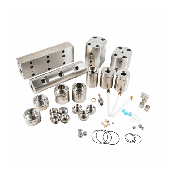
Repair kit
Major maintenance kit, 050624-2
Note: All components should be clean and free of debris prior to assembly. Keeping the work area clean
is important while working on the equipment.
SB-0259 Rev A Status: PRODUCTION
2011 Flow International Corporation
Failure to follow these step-by-step instructions and the procedures in your FLOW
service manual could result in premature failure or damage to the equipment.
UNCONTROLLED COPY
Installing the HyPlex® Prime
Major Maintenance Kit
CAUTION
SB-0259
1 of 10
PRINTED 7/29/11
Advertisement

Subscribe to Our Youtube Channel
Related Manuals for Flow HyPlex Prime Major

Summary of Contents for Flow HyPlex Prime Major
- Page 1 Use the procedure in this service bulletin when installing the Major Maintenance Kit on your HyPlex Prime pump. This service is performed at every fourth required maintenance interval for the life of the equipment. The complete major maintenance kit schedule is listed in your FLOW service manual. Tools You will need the following tools: ...
-
Page 2: Parts Identification
When engaged on the tie rods, there should be no exposure of the piston shoulder. 2 of 10 SB-0259 Rev A Status: PRODUCTION 2011 Flow International Corporation UNCONTROLLED COPY PRINTED 7/29/11... - Page 3 Remove the two o-rings from the outer diameter of the adapter. Discard the seal, o-ring, and snap ring. Keep the spacer for reuse. 3 of 10 SB-0259 Rev A Status: PRODUCTION 2011 Flow International Corporation UNCONTROLLED COPY PRINTED 7/29/11...
- Page 4 Re-wet the paper as needed. 20. Thoroughly clean the check valve body openings to remove particles from the lapping procedure. 4 of 10 SB-0259 Rev A Status: PRODUCTION 2011 Flow International Corporation UNCONTROLLED COPY PRINTED 7/29/11...
- Page 5 7. Secure the check valve body in the rebuild clamp with the inlet face downward. Torque the outlet cage to 30 ft-lb (41 N-m). Repeat Steps 1-7 for the remaining check valves. 5 of 10 SB-0259 Rev A Status: PRODUCTION 2011 Flow International Corporation UNCONTROLLED COPY PRINTED 7/29/11...
- Page 6 4. Lubricate and install the two o-rings onto the adapter, and slide the adapter over the plunger until it engages the counterbore of the subplate. Repeat steps 1-3 for the remaining subplate adapters 6 of 10 SB-0259 Rev A Status: PRODUCTION 2011 Flow International Corporation UNCONTROLLED COPY PRINTED 7/29/11...
- Page 7 2. Apply pressure to the spring and rotate counterclockwise until it snaps into place. Be sure the spring is firmly attached. Repeat for the remaining inlet poppets. 7 of 10 SB-0259 Rev A Status: PRODUCTION 2011 Flow International Corporation UNCONTROLLED COPY PRINTED 7/29/11...
- Page 8 6. Install washers and hex nuts hand tight. 7. Remove the temporarily installed hex nuts. Apply anti-seize to both sides of the washers and threads, then reinstall the nuts. 8 of 10 SB-0259 Rev A Status: PRODUCTION 2011 Flow International Corporation UNCONTROLLED COPY PRINTED 7/29/11...
- Page 9 11. Loosely thread the other end of each of the three tubes into the end cap ports. 12. Once in place, tighten all six gland nuts. 13. Reconnect all high-pressure and low-pressure interface connect 9 of 10 SB-0259 Rev A Status: PRODUCTION 2011 Flow International Corporation UNCONTROLLED COPY PRINTED 7/29/11...
- Page 10 4. Follow the start-up procedure in your service manual before returning the HyPlex Prime pump to service. 10 of 10 SB-0259 Rev A Status: PRODUCTION 2011 Flow International Corporation UNCONTROLLED COPY PRINTED 7/29/11...
Need help?
Do you have a question about the HyPlex Prime Major and is the answer not in the manual?
Questions and answers