Table of Contents
Advertisement
Quick Links
Advertisement
Table of Contents

Subscribe to Our Youtube Channel
Related Manuals for Brofer MDF30EURO

Summary of Contents for Brofer MDF30EURO
- Page 1 INSTALLATION AND OPERATION MANUAL FIRE PROTECTION MDF30EURO making air better...
-
Page 2: Table Of Contents
EUROPEAN FIRE DAMPERS CERTIFIED ACCORDING TO EN 15650 SERIE MDF30EURO 0497/CPD/5018 INDEX SPECIFICATIONS / GENERAL DESCRIPTION pag 3 REGULATORY FRAMEWORK HANDLING AND INSTALLATION WARNINGS MAINTENANCE INSTALLATION IN BRICK WALLS INSTALLATION IN CONCRETE FLOORS INSTALLATION IN LIGHTWEIGHT WALLS CONTROL FUNCTIONS REPLACING THE MECHANICAL FUSE 10. -
Page 3: Pag
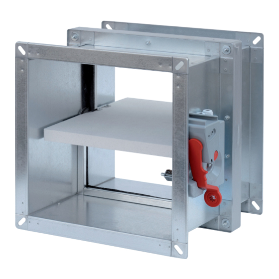
1. SPECIFICATIONS / GENERAL DESCRIPTION Fire damper suitable for wall or ceiling installation (horizontal or vertical), made from zinc-plated steel pipes and components, shutter and thermal cutting in single calcium silicate sheets 30 mm thick with perimeter seals to ensure conformity with sealing requirements for both cold fumes and hot fumes. -
Page 4: Handling And Installation Warnings
3. HANDLING AND INSTALLATION WARNINGS WARNING! • All handling and installation operations must be conducted with the fire damper shutter in a closed position (as per our standard supply). • All connections to the mains must be done by professionally qualified personnel. •... -
Page 5: Installation In Brick Walls
5. INSTALLATION IN BRICK WALLS 1 Before commencing installation, check the condition of the damper, the correct position of the shutter, in a closed position, and that the command works properly. 2 Make a hole in the wall which is 120 mm large in H and L than the nominal damper measurements (fig.1). 3 Position the damper inside the hole centring it horizontally, making sure the shutter axis corresponds to the wall axis. -
Page 6: Installation In Concrete Floors
6. INSTALLATION IN CONCRETE FLOORS 1 Before commencing installation, check the condition of the damper, the correct position of the shutter, in a closed position, and that the command works properly. 2 Make a hole in the wall which is 150 mm large in H and L than the nominal damper measurements, and position the metal brackets accessories (only when positioning it with the command side above the floor) aligning them with the edge of the hole (fig. -
Page 7: Installation In Lightweight Walls
7. INSTALLATION IN LIGHTWEIGHT WALLS 1 Before commencing installation, check the condition of the damper, the correct position of the shutter, in a closed position, and that the command works properly. The plasterboard panels to be used are of type F according to EN 520 and DIN 18180 and have unit thickness of 12,5 mm. -
Page 8: Control Functions
8. CONTROL FUNCTIONS Manual Mode Reset: • Remove the reset lever from the housing compartment (fig.1). • Insert the reset lever inside the control pin as far as possible, turning the lever clockwise by 90 degrees, making sure that the control pin is blocked in the open position (fig.2). •... -
Page 9: Replacing The Mechanical Fuse
Manual command with input electromagnet Reset: • Raise the metal lever on the control unit casing (fig.1). • Remove the reset lever from the housing compartment (fig.2). • Insert the reset lever inside the control pin as far as possible, turning the lever clockwise by 90 degrees, making sure that the control pin is blocked in the open position (fig.3). -
Page 10: Manual Command Functions, Data And Electrical Wiring Layout
10. MANUAL COMMAND FUNCTIONS, DATA AND ELECTRICAL WIRING LAYOUT Start and end stroke microswitches The devices that signal the start stroke and end stroke are two independent NC+NO dual contact switches. The first normally closed (NC) on contacts 21 and 22, whilst the second normally open (NO) on contacts 13 and 14. -
Page 11: Motorised Command Functions, Data And Electrical Wiring Layout
11. MOTORISED COMMAND FUNCTIONS, DATA AND ELECTRICAL WIRING LAYOUT The motor is powered by connecting it to the mains (contacts 1 and 2) which moves the damper shutter to the open position, whilst simultaneously loading the spring which retains all the power needed to close the duct in case of and alarm or black-out. - Page 12 BROFER SRL - Via Roma, 66 - 31023 Resana (TV) Italy Tel. +39 0423 716611 - Fax +39 0423 716612 - info@brofer.it - www.brofer.it Μιχαήλ Καραολή 19 143 43, Ν. Χαλκηδόνα, Αθήνα, Τηλ: 211 - 70.55.500 & 210 - 21.30.051, Fax: 210 - 22.23.283...
Need help?
Do you have a question about the MDF30EURO and is the answer not in the manual?
Questions and answers