Advertisement
Quick Links
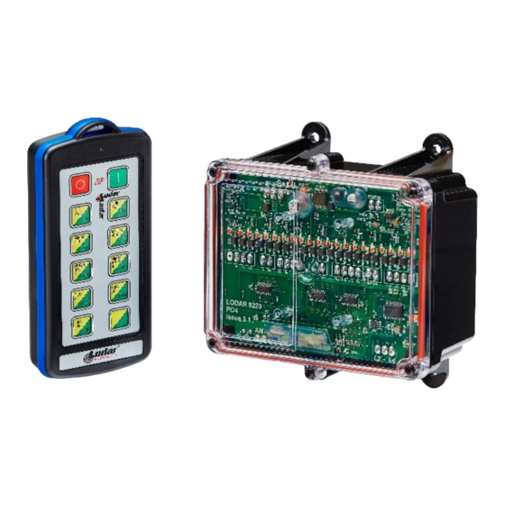
20 Function and IP Extend Transmitter
SYSTEM PART NUMBER
92320
1 x 20 Function Receiver & 1 x 10 Function Extend Transmitter
(20 Function in Extend Mode)
TRANSMITTER SPECIFICATION
ENCLOSURE
Material
Switch Type
Functions
Identification
RF
Modulation
Frequency
Channels
Channel Selection
Technology
Temperature Range
Range
Aerial
Transmitted power
POWER
Batteries
Quiescent Current
Current Transmitting
PROTECTION
IP Rating
Registration codes
INDICATOR
Type
Off
Slow flash
On
Fast flash
Enclosure Slow Flash
COMPLIANCE
FCC
IC
RoHS
ABS
Tactile Dome on PCB Keypad
10 (20 with dual function buttons)
Pockets for printed text or image insertion
2-GFSK. Gaussian Frequency Shift Keying
433.050 MHz to 434.790 MHz
1
Fixed
Hand-held Transmitter
o
o
o
-10
C to + 40
C (13
F to + 104
60m (200ft)
Internal – printed on PCB
1mW Typical
4 x AAA Alkaline Manganese in holder (6 Volts)
15µA
20mA
65
Over 16 million
1 x Red LED
Transmitter is OFF and in standby mode
Transmitter is ON and ready for use (The SET Button has been pressed and released)
Transmitting (A STOP, SET or Function Button is being pressed)
Transmitting – Indication that the battery will need replacing soon
ON and ready for use with Receiver 2. The SET button has been pressed and released
FCC CFR 47-part 15.231
433.9MHz
ISED RSS-210 Issue 8
433.9MHz
Directive
2011/65/EU
REPLACEMENT TRANSMITTER
92310TX - 10 Function IP Transmitter with
Extend Buttons.(20 Function in Extend Mode)
REPLACEMENT RECEIVER
9220RX - 20 Function Receiver
o
F). Use Lithium for lower temperatures
w92320.09
CONTENTS
1 x Receiver
1 x IP Extend Transmitter
1 x Lanyard
1 x Instructions
Advertisement

Summary of Contents for Lodar 92320
- Page 1 20 Function and IP Extend Transmitter SYSTEM PART NUMBER CONTENTS 92320 1 x 20 Function Receiver & 1 x 10 Function Extend Transmitter 1 x Receiver (20 Function in Extend Mode) 1 x IP Extend Transmitter 1 x Lanyard 1 x Instructions...
-
Page 2: Receiver Specification
RECEIVER SPECIFICATION ELECTRICAL Voltage Nominal 12/24V DC Voltage Min/Max 8 to 36V DC Switch Type MOSFET (Positive Switching) Modulation 2-GFSK. Gaussian Frequency Shift Keying Frequency 433.050 MHz to 434.790 MHz 902.025 MHz– 927.975 MHz Channels Channel Selection Fixed Channel hopping Technology Fixed Receiver Temperature Range... - Page 3 ENCLOSURE Weight 0.5 lbs (335gms) Clear PC/FR V0 and UV stabilised Base Black PC V0 and UV stabilised Breather Gortex fitted in base Mounting 4 external lugs Fixings 5mm (3/16”) not supplied IP Rating IP55 92 Series BUILD SPECIFICATION TABLE FOR MODELS IN THIS RANGE Ident Legend Connection...
- Page 4 COMPLIANCE REG 10 EC Type-approval mark E11 037601 EC Type-approval No: e11/72/245*2009/19*7601*00 FCC CFR 47 Part 15.109 433.050MHz to 434.790MHz FCC CFR 47 Part 15.109 902.025MHz to 927.975MHz ICES-003 Issue 6. 433.050MHz to 434.790MHz ICES-003 Issue 6. 902.025MHz to 927.975MHz RED Directive ETSI EN 300 220-2 v3.2.
- Page 5 EXPLANATION OF “SHIFT” & “EXTEND” OPERATIONS - as illustrated with a 20 Function Transmitter. These “SHIFT” operations can be applied to ALL Transmitters. For example, a 10 function Transmitter will give 20 functions – ideal if you do not want the larger 20 function Transmitter. To operate 2 x 20 function Receivers, giving 40 functions This is a standard 20 function Transmitter, modified so that it transmits 20 functions in two different modes.
Need help?
Do you have a question about the 92320 and is the answer not in the manual?
Questions and answers