Table of Contents

Related Manuals for Binsfeld TorqueTrak 9000

Summary of Contents for Binsfeld TorqueTrak 9000
- Page 1 TorqueTrak 9000 Digital Telemetry System Users Manual Featuring TorqueTrak All-Digital Technology Binsfeld Engineering Inc. 4571 W. MacFarlane Maple City, MI 49664 800-524-3327 231-334-4383 FAX: 231-334-4903 www.binsfeld.com 8690009C...
-
Page 2: Table Of Contents
BT9000 Bridge Transmitter ............ 7 Set Up Procedure ..............8 Appendix A: Calibration Verification ......... 12 Appendix B: TorqueTrak 9000 Specifications ......13 Appendix C: Calibration Calculations ........15 C1: Torque on Round Shafts ..........16 C2: Axial Strain on Round Shafts ......... 19 C3: Single Grid (1/4 Bridge) .......... - Page 3 FCC Rules Part 15: Computing Devices This equipment has been tested and found to comply with the limits for a Class B digital device, pursuant to part 15 of the FCC Rules The user is cautioned that changes and modifications made to the equipment without the express approval of the manufacturer could void the user’s authority to operate this equipment.
-
Page 4: System Overview
excellent accuracy and stability minimal drift with ambient temperature changes microprocessor-based digital circuitry from sensor input to signal output Ideal for short term diagnostic testing, the TorqueTrak 9000 is rugged, intelligent, and simple to use. - 3 -... -
Page 5: System Components
(220VAC/12VDC Wall Plug Transformer optional) RA900 Receiver Antenna (magnetic mount base) with 25 ft connecting cable BS900 Bridge Simulator Screwdriver 9V lithium battery Rubber sheet 10ft 4-conductor ribbon cable Desoldering braid 1 roll 1” fiberglass tape TorqueTrak 9000 Users Manual - 4 -... -
Page 6: Features And Controls
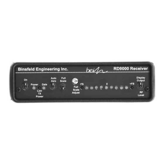
Features and Controls RD9000 Receiver Full Scale Switch In up position, receiver generates positive full scale voltage signal at Output (can be attenuated with Full Scale Adjust). In down position, receiver outputs live data signal (from transmitter). Full Scale Adjust Low TX Power Reduces amplitude of Blinking light indicates low... - Page 7 Antenna Voltage Output Power Input Jack Connect to RA900 Connect to chart recorder Connect to 12VDC antenna using SMA- or other read-out device. (e.g. wall plug SMA cable. (±10V Full Scale) transformer). Filter Switch RF Channel Selector Switch to up position to Adjust receiver knob to match RF apply 10Hz low-pass filter transmit frequency of BT9000...
-
Page 8: Bt9000 Bridge Transmitter
BT9000 Bridge Transmitter To sensor (gage): -Exc: Black -Sen: White +Sen: Green +Exc: Red To 9V battery negative To 9V battery positive Gain Select pads (See Appendix E.) RF Channel Select pads (See Appendix D.) - 7 -... -
Page 9: Set Up Procedure
Set Up Procedure Before installing the telemetry it is important to verify that the gain setting of the transmitter is suitable for the expected sensor load. (The BT9000 transmitter is factory set for a gain of 2000 (Gain Level = 4) which will accommodate most torque applications.) To determine the appropriate gain setting for a given application refer to the calculations in Appendix C. - Page 10 Battery Clip Sensor (strain gage shown) Transmitter, Battery and Sensor Connections 5. Using the provided 25ft coax antenna cable connect the RA900 receiving antenna to Antenna connection on rear panel of RD9000 receiver. 6. Position RA900 magnetic-mount receiving antenna near transmitter, typically within 10 feet.
- Page 11 RD9000 Front Panel 8. Flip AutoZero switch down to remove the previously stored reference. Confirm that Full Scale switch is down (used only for scaling and trouble shooting). 9. Confirm that Data light on front panel of RD9000 is on solid (indicating successful data transmission).
- Page 12 (3) replace the strain gage. For further assistance, contact technical support at Binsfeld Engineering. 13. Set Filter switch at rear of RD9000 to desired position, up to activate 10 Hz low-pass filter (averages dynamic data) or down to allow full 500 Hz frequency response.
-
Page 13: Appendix A: Calibration Verification
It is recommended that the RD9000 be checked for calibration annually. If found to be out of specification, it can be returned to Binsfeld Engineering Inc. for calibration for a nominal fee ($100.00, price subject to change). - 12 -... -
Page 14: Appendix B: Torquetrak 9000 Specifications
Appendix B: TorqueTrak 9000 Specifications BT9000 Transmitter Sensor Input: Full (4-arm) Wheatstone Bridge strain gage (120-1000 ohms; 350 ohms standard) Bridge Input: 5.0VDC, regulated Sensor Range: User selectable. See tables below. Transmitter Torque, Gain Gain Bending Level Full Bridge, 4 Active Arms 8000 ±125 microstrain... - Page 15 Transmitter g-force Rating: 3000 g’s (steady state) Operating Temperature: 0 to 70°C (32 to 158°F) 1.05” x 1.95” x 0.70” Size and Weight: (27mm x 50mm x 18mm) (57g) RD9000 Receiver Output Signal: ±10VDC, field adjustable down to ± 5VDC Output Connection: 5-way binding posts (banana jacks) Power Input:...
-
Page 16: Appendix C: Calibration Calculations
The equations in this Appendix define the relationship between the input signal to the BT9000 transmitter (typically from a strain gage) and the full scale output voltage of the TorqueTrak 9000 system. The calculations are based on parameters of the device being measured (e.g. -
Page 17: C1: Torque On Round Shafts
C1: Torque on Round Shafts Step 1: Calculate Full Scale Torque, T (ft-lb) that corresponds to the maximum system output of 10.0V. For a solid steel shaft, use this simplified equation: (755.17 x 10 ft-lb/in (ft-lb) (GF) (G For all other shafts use the more general equation: )()(E)(4)(D (ft-lb) )(GF)(N)(16)(1+)(G... - Page 18 Example: Given a solid steel shaft with (shaft diameter, measured) = 2.5 inches GF (gage factor from gage package) = 2.045 (BT9000 gain based on jumpers) = 2000 (755.17 x 10 ft-lb/in )(2.50 in) = 2,885 ft-lb (2.045) (2000) so 10.0 V output at the RD9000 indicates 2,885 ft-lb of torque or 288.5 ft-lb/volt.
- Page 19 Example: The full scale torque (T ) has been calculated to be 2,885 ft-lb, for 10 volts. However the user would like to scale the system output to an adjusted torque (T ) of 4,000 ft-lb for 10 volts. (Note that TRIM = 4,000 is greater than T = 2,885.)
-
Page 20: C2: Axial Strain On Round Shafts
C2: Axial Strain on Round Shafts Step 1: Calculate Full Scale Forces P (lb) that corresponds to the maximum system output of 10.0V. For a solid steel shaft, use this simplified equation: (72.50 x 10 lb/in (GF) (G For all other shafts use the more general equation: )()(E)(D )(GF)(2)(1+)(G Legend of Terms... - Page 21 Example: Given a solid steel shaft with (shaft diameter, measured) = 2.25 inches GF (gage factor from gage package) = 2.045 (BT9000 gain based on jumpers) = 2000 (72.50 x 10 lb/in )(2.25 in) = 89,736 lb (2.045) (2000) so 10.0 V output at the RD9000 indicates 89,736 lb of force or 8974 lb/volt.
- Page 22 Example: The full scale force (P ) has been calculated to be 89,736 lb for 10 volts. However the user would like to scale the system output to an adjusted force ) of 100,000 lb for 10 volts. (Note that P TRIM TRIM 100,000 is greater than P...
-
Page 23: C3: Single Grid (1/4 Bridge)
C3: Single Grid (1/4 Bridge) Step 1: Calculate Full Scale Strain, (inches/inch) that corresponds to the maximum system output of 10.0V. )(4) )(GF)(G Using the values listed in the table below, this equation reduces (GF)(G Legend of Terms Full Scale Strain (inches/inch;... - Page 24 Example: GF (gage factor from gage package) = 2.045 (BT9000 gain based on jumpers) = 2000. = 1956 x 10 inches/inch (2.045)(2000) so 10.0 V output at the RD9000 indicates 1956 microstrain or 196 microstrain/volt. Step 2: Trim the Full Scale Output: If desired, the full scale output voltage of the RD9000 can be trimmed so that the voltage output corresponds to an even round number strain level, e.g.
- Page 25 Example: The full scale strain ( ) has been calculated to be 1956 microstrain for 10 volts. However the user would like to scale the system output to an adjusted strain ( ) of 2000 microstrain for 10 volts. (Note TRIM ...
-
Page 26: Appendix D: Rf Channel Configuration
Appendix D: RF Channel Configuration The RF frequency of the RD9000 receiver is selected simply by switching the RF Channel knob on the rear panel to the desired channel (0-7). To change the RF frequency of the BT9000 transmitter, configure the three RF Channel Select pads on the exposed circuit board of the transmitter according to the following table. -
Page 27: Appendix E: Transmitter Gain Configuration
Appendix E: Transmitter Gain Configuration To change the gain setting of the BT9000 transmitter, configure the three Gain Select pads on the exposed circuit board of the transmitter according to the following table. To add a jumper simply form a solder bridge connection across the two rectangular solder pads. -
Page 28: Appendix F: Trouble Shooting Guide
Appendix F: Trouble Shooting Guide Symptom: No data (data light off) Problem/Cause Solution/Corrective Action Low battery voltage Check transmitter power supply (measure voltage at “+9V” relative to at transmitter “Gnd”). Check transmitter battery connections. Mismatched Double check jumper settings on frequencies transmitter. - Page 29 Bridge too far out of Shunt one arm of bridge with resistor to balance as installed bring gage into balance (Contact Binsfeld Engineering Technical Support. Request BB900 Bridge Balancer.) Symptom: Flickering “Data” light, spikes in data signal Problem/Cause Solution/Corrective Action...
-
Page 30: Appendix G: Strain Gage Application
Appendix G: Strain Gage Application (Also refer to instruction bulletin B-127-12 provided with GAK-2- 200 Strain Gage Application Kit) PREPARING THE SURFACE 1. A 3-inch square area will be used for gaging. Scrape off any paint or other coatings and inspect shaft for oil residue. - Page 31 PREPARING THE GAGE FOR MOUNTING 5. Using tweezers, remove one gage from its package. Using the plastic gage box as a clean surface, place the gage on it, bonding side down. Take a 6” piece of PCT- 2A Cellophane Tape and place it on the gage and terminal, centered.
- Page 32 7. Gage should now be positioned. Once again, lift the gage end of the tape at a shallow angle to the surface until the gage is free of the surface. Continue pulling the tape until you are approximately 1/8” – 1/4” beyond gage.
- Page 33 glue line to move up and across the gage area. A very thin, uniform layer of adhesive is desired for optimum bond performance. 11. Immediately, using your thumb, apply firm pressure to the taped gage by rolling your thumb over the gage area. Hold the pressure for at least one minute.
- Page 34 - 33 -...
- Page 35 Maple City, MI 49664. BEI assumes no risk for damage in transit. Binsfeld Engineering Inc. will, at its option, repair or replace the defective equipment during the warranty period. However, if we determine that the failure was caused by misuse, alteration or...
Need help?
Do you have a question about the TorqueTrak 9000 and is the answer not in the manual?
Questions and answers