Table of Contents
Advertisement
Available languages
Available languages
Advertisement
Chapters
Table of Contents

Related Manuals for Lenze EZN3 0110H030 Series


Summary of Contents for Lenze EZN3 0110H030 Series
- Page 1 EDKZNXXXX−002 .Aô{ Montageanleitung Mounting Instructions Instructions de montage Global Drive 30 ... 110 A EZN3x0110H030, EZN3x0080H042, EZN3x0055H060, EZN3x0037H090, EZN3x0030H110 Anbau−Netzfilter Built−on mains filter Filtre réseau latéral...
- Page 2 Lesen Sie zuerst diese Anleitung und die Dokumentation zum Grundgerät, bevor Sie mit den Arbeiten beginnen! Beachten Sie die enthaltenen Sicherheitshinweise. Please read these instructions and the documentation of the standard device before you start working! Observe the safety instructions given therein! Lire le présent fascicule et la documentation relative à...
-
Page 3: Table Of Contents
Inhalt Über diese Dokumentation ..........Informationen zur Gültigkeit . -
Page 4: Über Diese Dokumentation
Erstausgabe 13216423 10/2007 TD29 Überarbeitung .Aô{ 02/2010 TD29 Überarbeitung Tipp! Dokumentationen und Software−Updates zu weiteren Lenze Produkten finden Sie im Internet im Bereich "Services & Downloads" unter http://www.Lenze.com Verwendete Konventionen Informationsart Auszeichnung Beispiele/Hinweise Zahlenschreibweise Dezimaltrennzeichen Punkt Es wird generell der Dezimalpunkt verwen- det. -
Page 5: Verwendete Hinweise
Über diese Dokumentation Verwendete Hinweise Verwendete Hinweise Um auf Gefahren und wichtige Informationen hinzuweisen, werden in dieser Dokumenta- tion folgende Piktogramme und Signalwörter verwendet: Sicherheitshinweise Aufbau der Sicherheitshinweise: Gefahr! (kennzeichnet die Art und die Schwere der Gefahr) Hinweistext (beschreibt die Gefahr und gibt Hinweise, wie sie vermieden werden kann) Piktogramm und Signalwort Bedeutung Gefahr von Personenschäden durch gefährliche elektrische... -
Page 6: Sicherheitshinweise
Schaltungsausschnitte sind Vorschläge, deren Übertragbarkeit auf die jeweilige Anwendung überprüft werden muss. Für die Eignung der angegebenen Verfahren und Schaltungsvorschläge übernimmt der Hersteller keine Gewähr. Alle Arbeiten mit und an Lenze−Antriebskomponenten darf nur qualifiziertes ƒ Fachpersonal ausführen. Nach IEC 60364 bzw. CENELEC HD 384 sind dies Personen, ... -
Page 7: Restgefahren
Sicherheitshinweise Restgefahren Restgefahren Gefahr! Gefährliche elektrische Spannung Alle Leistungsanschlüsse führen bis zu 3 Minuten nach Netz−Ausschalten gefährliche elektrische Spannung. Mögliche Folgen: Tod oder schwere Verletzungen beim Berühren der Leistungsanschlüsse. ƒ Schutzmaßnahmen: Vor Arbeiten an den Leistungsanschlüssen Netz abschalten und mindestens ƒ... - Page 8 Sicherheitshinweise Restgefahren Stop! Hohes Gerätegewicht Das Gerät ist sehr schwer und muss für die Montage angehoben werden. Mögliche Folgen: Personenschäden, insbesondere Rückenschäden beim Anheben bzw. Halten ƒ des Gerätes Sach− und Personenschäden durch Herunterfallen des Gerätes ƒ Schutzmaßnahmen: Gerät nur mit einer für das Gerätegewicht zugelassenen ƒ...
-
Page 9: Produktbeschreibung
Bestimmungsgemäße Verwendung Produktbeschreibung Bestimmungsgemäße Verwendung Netzfilter und Funk−Entstörfilter sind Zusatzeinheiten für Lenze−Antriebsregler. ƒ nur an Lenze−Antriebsregler anschließen, wenn dazu die Vorgaben in der ƒ Dokumentation zum Antriebsregler erfüllt werden. nur unter den in dieser Betriebsanleitung vorgeschriebenen Einsatzbedingungen ƒ betreiben. sind Komponenten ƒ... -
Page 10: Übersicht
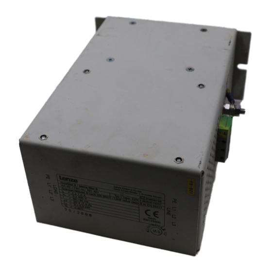
Produktbeschreibung Übersicht Übersicht EZN−031 Position Beschreibung Netzanschluss PE−Gewindebolzen Anschluss Grundgerät Typenschild Anschluss Thermokontakt Befestigungswinkel Schirmblech Thermokontakt−Leitung (im Beipack) EDKZNXXXX−002 DE/EN/FR 3.0... -
Page 11: Identifikation
Produktbeschreibung Identifikation Identifikation Hans-Lenze-Straße 1 D-31855 Aerzen Made in Germany Type: 8200vec080 Abb. 3−1 Typenschild Typenschlüssel xxxx xxxx Produktreihe Zubehör Filtertyp N = Netzfilter Anzahl Phasen 3 = 3 Phasen Grenzwertklasse nach EN 61800−3 A = Grenzwertklasse C2 B = Grenzwertklasse C1 Induktivität... -
Page 12: Technische Daten
Technische Daten Allgemeine Daten und Einsatzbedingungen Technische Daten Allgemeine Daten und Einsatzbedingungen Angaben zu Netzen Netzformen Mit geerdetem Y−Punkt (TT−/TN−Netze) Betrieb uneingeschränkt erlaubt Andere Netzformen Anweisungen über besondere Maßnahmen in der Dokumen- tation zum Grundgerät beachten! Schutz Schutzart EN 60529 IP 20 nicht im Anschlussbereich der Klemmen... -
Page 13: Bemessungsdaten
Technische Daten Bemessungsdaten Bemessungsdaten Grundlage der Daten Netz Spannung Spannungsbereich Frequenzbereich f [Hz] 3/PE AC 320 − 0 % ... 440 + 0 % 45 − 0 % ... 65 + 0 % 3/PE AC 432 − 0 % ... 528 + 0 % 45 ... -
Page 14: Mechanische Daten
Technische Daten Mechanische Daten Mechanische Daten Alle Maße in Millimeter. Bauform 1 EZN−032a Masse [kg] EZN3A0110H030 15.9 EZN3A0080H042 17.8 Bauform 2 EZN−032d Masse [kg] EZN3B0110H030 14.2 EZN3B0080H042 16.1 EDKZNXXXX−002 DE/EN/FR 3.0... - Page 15 Technische Daten Mechanische Daten Bauform 3 EZN−032b Masse [kg] EZN3A0055H060 31.0 EZN3B0055H060 30.5 Bauform 4 EZN−032c Masse [kg] EZN3A0037H090 38.5 EZN3B0037H090 40.5 EZN3A0030H110 40.5 EZN3B0030H110 47.0 EDKZNXXXX−002 DE/EN/FR 3.0...
-
Page 16: Mechanische Installation
Mechanische Installation Wichtige Hinweise Mechanische Installation Wichtige Hinweise Der Montageort muss den in den Technischen Daten genannten ƒ Einsatzbedingungen immer entsprechen (¶ 12). Ggf. zusätzliche Maßnahmen ergreifen. Die Montageplatte des Schaltschranks muss folgende Eigenschaften aufweisen: ƒ – elektrisch leitfähig – lackfrei Die mechanischen Verbindungen müssen immer gewährleistet sein. -
Page 17: Montageschritte
Mechanische Installation Montageschritte Montageschritte Bauform 1 und 2 EZN3A0110H030 ƒ EZN3A0080H042 ƒ EZN3B0110H030 ƒ EZN3B0080H042 ƒ EZN−034a So montieren Sie das Filter: 1. Lesen Sie in der Dokumentation des Grundgerätes das Kapitel "Mechanische Installation". Informieren Sie sich insbesondere über ... –... - Page 18 Mechanische Installation Montageschritte Bauform 3 und 4 EZN3A0055H060 ƒ EZN3B0055H060 ƒ EZN3A0037H090 ƒ EZN3A0030H110 ƒ EZN3B0037H090 ƒ EZN3B0030H110 ƒ EZN−034b So montieren Sie das Filter: 1. Lesen Sie in der Dokumentation des Grundgerätes das Kapitel "Mechanische Installation". Informieren Sie sich insbesondere über ... –...
-
Page 19: Elektrische Installation
Elektrische Installation Wichtige Hinweise Elektrische Installation Wichtige Hinweise Die Installation muss ƒ – den in den Technischen Daten genannten Einsatzbedingungen immer entsprechen (¶ 12). – nach EN 60204−1 ausgeführt werden. Bei der Auswahl des Leitungstyps beachten: ƒ – Die verwendeten Leitungen müssen den geforderten Approbationen am Einsatzort entsprechen (z. -
Page 20: Anschlussdaten
Elektrische Installation Anschlussdaten Anschlussdaten Klemmen "Line" [Nm] [AWG] [mm] [lb−in] EZN3x0110H030 2 ... 2.3 0.5 ... 16 0.5 ... 6 20 ... 4 17.7 ... 20.35 EZN3x0080H042 4 ... 4.5 EZN3x0055H060 10 ... 25 4 ... 25 2.5 ... 10 10 ... -
Page 21: Montageschritte
Elektrische Installation Montageschritte Montageschritte Bauform 1 EZN3A0110H030 ƒ EZN3A0080H042 ƒ EZNx035a So verdrahten Sie das Filter: 1. Schaltschrank spannungsfrei schalten und gegen wiedereinschalten sichern. 2. Anschlussleitungen "Load" 2 am Grundgerät anschließen. – Montageanleitung des Grundgerätes beachten! 3. PE−Leiter mit Ringkabelschuh an PE−Gewindebolzen 1 montieren. –... - Page 22 Elektrische Installation Montageschritte Bauform 2 EZN3B0110H030 ƒ EZN3B0080H042 ƒ EZNx035b So verdrahten Sie das Filter: 1. Schaltschrank spannungsfrei schalten und gegen wiedereinschalten sichern. 2. Anschlussleitungen "Load" 2 am Grundgerät anschließen. – Montageanleitung des Grundgerätes beachten! 3. Netzleitungen (L1, L2, L3, PE) an Schraubklemme "Line" 0 anschließen. –...
- Page 23 Elektrische Installation Montageschritte Bauform 3 EZN3A0055H060 ƒ EZN3B0055H060 ƒ EZNx035c So verdrahten Sie das Filter: 1. Schaltschrank spannungsfrei schalten und gegen wiedereinschalten sichern. 2. Anschlussleitungen "Load" 2 am Grundgerät anschließen. – Montageanleitung des Grundgerätes beachten! 3. PE−Leiter mit Ringkabelschuh an PE−Gewindebolzen 1 montieren. –...
- Page 24 Elektrische Installation Montageschritte Bauform 4 EZN3A0037H090 ƒ EZN3A0030H110 ƒ EZN3B0037H090 ƒ EZN3B0030H110 ƒ EZNx035d So verdrahten Sie das Filter: 1. Schaltschrank spannungsfrei schalten und gegen Wiedereinschalten sichern. 2. Anschlussleitungen "Load" 2 am Grundgerät anschließen. – Montageanleitung des Grundgerätes beachten! 3. PE−Leiter mit Ringkabelschuh an PE−Gewindebolzen 1 montieren. –...
- Page 25 Contents About this documentation ..........Validity information .
-
Page 26: About This Documentation
10/2007 TD29 Revision .Aô{ 02/2010 TD29 Revision Tip! Documentation and software updates for further Lenze products can be found on the Internet in the "Services & Downloads" area under http://www.Lenze.com Conventions used Type of information Identification Examples/notes Spelling of numbers... -
Page 27: Notes Used
About this documentation Notes used Notes used The following pictographs and signal words are used in this documentation to indicate dangers and important information: Safety instructions Structure of safety instructions: Danger! (characterises the type and severity of danger) Note (describes the danger and gives information about how to prevent dangerous situations) Pictograph and signal word Meaning... -
Page 28: Safety Instructions
– The specifications, processes, and circuitry described in this document are for guidance only and must be adapted to your own application. Lenze does not take responsibility for the suitability of the process and circuit proposals. Only qualified personnel may work with and on Lenze drive components. -
Page 29: Residual Hazards
Safety instructions Residual hazards Residual hazards Danger! Dangerous electrical voltage All power terminals remain live for up to three minutes after mains disconnection. Possible consequences: Death or severe injuries when touching the power terminals. ƒ Protective measures: Switch off the power supply and wait for at least three minutes before ƒ... - Page 30 Safety instructions Residual hazards Stop! Heavy device weight The device is very heavy and must be lifted for the mounting. Possible consequences: Injury to persons, particularly backache when lifting and holding the device, ƒ respectively Injury to persons and damage to material assets due to the device falling ƒ...
-
Page 31: Product Description
Mains filters and RFI filters are units which can be used with Lenze controllers. ƒ may only be connected to Lenze controllers if the requirements of the ƒ documentation for the controller are met. may only be operated under the operating conditions specified in these operating ƒ... -
Page 32: Overview
Product description Overview Overview EZN−031 Position Description Mains connection PE stud Basic device connection Nameplate Connection of the thermal contact Fixing bracket Shield sheet for the thermal contact cable (from the accessory kit) EDKZNXXXX−002 DE/EN/FR 3.0... -
Page 33: Identification
Product description Identification Identification Hans-Lenze-Straße 1 D-31855 Aerzen Made in Germany Type: 8200vec080 Fig. 3−1 Nameplate Type code xxxx xxxx Product series Accessories Type of filter N = mains filter Number of phases 3 = 3 phases Limit class according to EN 61800−3... -
Page 34: Technical Data
Technical data General data and operating conditions Technical data General data and operating conditions Mains data Mains types With grounded neutral (TT/TN systems) Operation permitted without restrictions Other mains types Observe instructions for special measures in the documentation for the basic device! Protection Degree of protection EN 60529... -
Page 35: Rated Data
Technical data Rated data Rated data Basis of the data Mains Voltage Voltage range Frequency range f [Hz] 3/PE AC 320 − 0 % ... 440 + 0 % 45 − 0 % ... 65 + 0 % 3/PE AC 432 −... -
Page 36: Mechanical Data
Technical data Mechanical data Mechanical data All dimensions in millimetres. Design 1 EZN−032a Type Mass [kg] EZN3A0110H030 15.9 EZN3A0080H042 17.8 Design 2 EZN−032d Type Mass [kg] EZN3B0110H030 14.2 EZN3B0080H042 16.1 EDKZNXXXX−002 DE/EN/FR 3.0... - Page 37 Technical data Mechanical data Design 3 EZN−032b Type Mass [kg] EZN3A0055H060 31.0 EZN3B0055H060 30.5 Design 4 EZN−032c Type Mass [kg] EZN3A0037H090 38.5 EZN3B0037H090 40.5 EZN3A0030H110 40.5 EZN3B0030H110 47.0 EDKZNXXXX−002 DE/EN/FR 3.0...
-
Page 38: Mechanical Installation
Mechanical installation Important notes Mechanical installation Important notes The mounting location must always fulfill the operating conditions specified in the ƒ Technical data. (¶ 34). If necessary, take additional measures. The mounting plate of the control cabinet must be: ƒ –... -
Page 39: Mounting Steps
Mechanical installation Mounting steps Mounting steps Design 1 and 2 EZN3A0110H030 ƒ EZN3A0080H042 ƒ EZN3B0110H030 ƒ EZN3B0080H042 ƒ EZN−034a How to mount the filter: 1. Read the chapter "Mechanical installation" in the documentation of the basic device. Read up particularly on ... –... - Page 40 Mechanical installation Mounting steps Designs 3 and 4 EZN3A0055H060 ƒ EZN3B0055H060 ƒ EZN3A0037H090 ƒ EZN3A0030H110 ƒ EZN3B0037H090 ƒ EZN3B0030H110 ƒ EZN−034b How to mount the filter: 1. Read the chapter "Mechanical installation" in the documentation of the basic device. Read up particularly on ... –...
-
Page 41: Electrical Installation
Electrical installation Important notes Electrical installation Important notes Installation must ƒ – always be in accordance with the operating conditions specified in the Technical data (¶ 34). – be carried out to EN 60204−1. Please observe the following when selecting the cable type: ƒ... -
Page 42: Connection Data
Electrical installation Connection data Connection data Terminals "line" [Nm] [AWG] [mm] [lb−in] EZN3x0110H030 2 ... 2.3 0.5 ... 16 0.5 ... 6 20 ... 4 17.7 ... 20.35 EZN3x0080H042 4 ... 4.5 EZN3x0055H060 10 ... 25 4 ... 25 2.5 ... 10 10 ... -
Page 43: Mounting Steps
Electrical installation Mounting steps Mounting steps Design 1 EZN3A0110H030 ƒ EZN3A0080H042 ƒ EZNx035a How to wire the filter: 1. Deenergise the control cabinet and fuse it against re−energisation. 2. Connect the connection cables "load" 2 to the basic device. – Observe the mounting instructions for the basic device! 3. - Page 44 Electrical installation Mounting steps Design 2 EZN3B0110H030 ƒ EZN3B0080H042 ƒ EZNx035b How to wire the filter: 1. Deenergise the control cabinet and fuse it against re−energisation. 2. Connect the connection cables "Load" 2 to the basic device. – Observe the mounting instructions of the standard device! 3.
- Page 45 Electrical installation Mounting steps Design 3 EZN3A0055H060 ƒ EZN3B0055H060 ƒ EZNx035c How to wire the filter: 1. Deenergise the control cabinet and fuse it against re−energisation. 2. Connect the connection cables "load" 2 to the basic device. – Observe the mounting instructions for the basic device! 3.
- Page 46 Electrical installation Mounting steps Design 4 EZN3A0037H090 ƒ EZN3A0030H110 ƒ EZN3B0037H090 ƒ EZN3B0030H110 ƒ EZNx035d How to wire the filter: 1. Deenergise the control cabinet and fuse it against re−energisation. 2. Connect the connection cables "Load" 2 to the basic device. –...
- Page 47 Sommaire Présentation du document ..........Informations relatives à...
-
Page 48: Présentation Du Document
TD29 Révision .Aô{ 02/2010 TD29 Révision Conseil ! Les mises à jour de logiciels et les documentations relatives aux produits Lenze sont disponibles dans la zone "Téléchargements" du site Internet : http://www.Lenze.com Conventions utilisées Type d’information Marquage Exemples/remarques Représentation des chiffres Séparateur décimal... -
Page 49: Consignes Utilisées
Présentation du document Consignes utilisées Consignes utilisées Pour indiquer des risques et des informations importantes, la présente documentation utilise les mots et symboles suivants : Consignes de sécurité Présentation des consignes de sécurité Danger ! (Le pictogramme indique le type de risque.) Explication (L’explication décrit le risque et les moyens de l’éviter.) Pictogramme et mot associé... -
Page 50: Consignes De Sécurité
Lenze n´assure pas sa responsabilité sur l´adaptabilité du procédé indiqué et des exemples de câblage pour l´application du client. Les travaux réalisés avec et au niveau des composants d’entraînement Lenze ne ƒ doivent être exécutés que par un personnel qualifié et habilité. -
Page 51: Dangers Résiduels
Consignes de sécurité Dangers résiduels Dangers résiduels Danger ! Tension électrique dangereuse Les raccordements de puissance sont encore sous tension jusqu’à 3 minutes après la coupure réseau. Risques encourus Mort ou blessures graves en cas de contact accidentel avec les ƒ... - Page 52 Consignes de sécurité Dangers résiduels Stop ! Appareil lourd Cet appareil est très lourd et doit être soulevé pour le montage. Risques encourus : Blessures, notamment lombalgies causées par le fait de soulever ou de ƒ maintenir l’appareil Blessures et dommages matériels causés par une chute de l’appareil ƒ...
-
Page 53: Description Du Produit
Les filtres réseau et les filtres antiparasites sont des unités complémentaires pour les variateurs de vitesse Lenze. ƒ ne doivent être raccordés aux variateurs de vitesse Lenze que si les prescriptions de ƒ la documentation sur le variateur de vitesse sont remplies. -
Page 54: Présentation
Description du produit Présentation Présentation EZN−031 Position Description Raccordement réseau Boulons filtetés PE Raccordement de l’appareil de base Plaque signalétique Raccordement pour contact thermique Equerres de fixation Tôle de blindage pour câble du contact thermique (comprise dans le kit de montage) EDKZNXXXX−002 DE/EN/FR 3.0... -
Page 55: Identification
Description du produit Identification Identification Hans-Lenze-Straße 1 D-31855 Aerzen Made in Germany Type: 8200vec080 Fig.3−1 Plaque signalétique Codification des types xxxx xxxx Série d’appareils Accessoires Type de filtre N = filtre réseau Nombre de phases 3 = 3 phases Classe d’antiparasitage suivant EN 61800−3... -
Page 56: Spécifications Techniques
Spécifications techniques Caractéristiques générales et conditions d’utilisation Spécifications techniques Caractéristiques générales et conditions d’utilisation Informations sur les réseaux Configurations réseau Avec point Y à la terre (réseaux TT/TN) Utilisation sans restriction Autres configurations réseau Respecter les indications concernant les mesures particulières dans la documentation de l’appareil de base ! Protection Indice de protection... -
Page 57: Caractéristiques Assignées
Spécifications techniques Caractéristiques assignées Caractéristiques assignées Données de base Réseau Tension Plage de tension Plage de fréquence f [Hz] 3/PE CA 320 − 0 % ... 440 + 0 % 45 − 0 % ... 65 + 0 % 3/PE AC 432 −... -
Page 58: Caractéristiques Mécaniques
Spécifications techniques Caractéristiques mécaniques Caractéristiques mécaniques Cotes en [mm] Forme de construction 1 EZN−032a Type Poids [kg] EZN3A0110H030 15.9 EZN3A0080H042 17.8 Forme de construction 2 EZN−032d Type Poids [kg] EZN3B0110H030 14.2 EZN3B0080H042 16.1 EDKZNXXXX−002 DE/EN/FR 3.0... - Page 59 Spécifications techniques Caractéristiques mécaniques Forme de construction 3 EZN−032b Type Poids [kg] EZN3A0055H060 31.0 EZN3B0055H060 30.5 Forme de construction 4 EZN−032c Type Poids [kg] EZN3A0037H090 38.5 EZN3B0037H090 40.5 EZN3A0030H110 40.5 EZN3B0030H110 47.0 EDKZNXXXX−002 DE/EN/FR 3.0...
-
Page 60: Installation Mécanique
Installation mécanique Remarques importantes Installation mécanique Remarques importantes Le lieu de montage doit toujours respecter les conditions d’utilisation indiquées ƒ dans les spécifications techniques (¶ 56). Si besoin est, prendre des mesures supplémentaires. La plaque de montage de l’armoire électrique doit être : ƒ... -
Page 61: Opérations De Montage
Installation mécanique Opérations de montage Opérations de montage Formes de construction 1 et 2 EZN3A0110H030 ƒ EZN3A0080H042 ƒ EZN3B0110H030 ƒ EZN3B0080H042 ƒ EZN−034a Pour monter le filtre : 1. Dans la documentation de l’appareil de base, lire le chapitre "Installation mécanique". - Page 62 Installation mécanique Opérations de montage Formes de construction 3 et 4 EZN3A0055H060 ƒ EZN3B0055H060 ƒ EZN3A0037H090 ƒ EZN3A0030H110 ƒ EZN3B0037H090 ƒ EZN3B0030H110 ƒ EZN−034b Pour monter le filtre : 1. Dans la documentation de l’appareil de base, lire le chapitre "Installation mécanique".
-
Page 63: Installation Électrique
Installation électrique Remarques importantes Installation électrique Remarques importantes L’installation doit ƒ – toujours respecter les conditions d’utilisation indiquées dans les spécifications techniques (¶ 56) ; – répondre aux exigences de la norme EN 60204−1. Lors du choix du type de câble, tenir compte des points suivants : ƒ... -
Page 64: Données De Raccordement
Installation électrique Données de raccordement Données de raccordement Bornes "Line" [Nm] [AWG] [mm] [lb−in] EZN3x0110H030 2 ... 2.3 0.5 ... 16 0.5 ... 6 20 ... 4 17.7 ... 20.35 EZN3x0080H042 4 ... 4.5 EZN3x0055H060 10 ... 25 4 ... 25 2.5 ... -
Page 65: Opérations De Montage
Installation électrique Opérations de montage Opérations de montage Forme de construction 1 EZN3A0110H030 ƒ EZN3A0080H042 ƒ EZNx035a Pour raccorder le filtre : 1. Couper la tension dans l’armoire électrique et s’assurer que toute mise sous tension est exclue. 2. Raccorder les câbles "Load" 2 à l’appareil de base. –... - Page 66 Installation électrique Opérations de montage Forme de construction 2 EZN3B0110H030 ƒ EZN3B0080H042 ƒ EZNx035b Pour raccorder le filtre : 1. Couper la tension dans l’armoire électrique et s’assurer que toute mise sous tension est exclue. 2. Raccorder les câbles "Load" 2 à l’appareil de base. –...
- Page 67 Installation électrique Opérations de montage Forme de construction 3 EZN3A0055H060 ƒ EZN3B0055H060 ƒ EZNx035c Pour raccorder le filtre : 1. Couper la tension dans l’armoire électrique et s’assurer que toute mise sous tension est exclue. 2. Raccorder les câbles "Load" 2 à l’appareil de base. –...
- Page 68 Installation électrique Opérations de montage Forme de construction 4 EZN3A0037H090 ƒ EZN3A0030H110 ƒ EZN3B0037H090 ƒ EZN3B0030H110 ƒ EZNx035d Pour raccorder le filtre : 1. Couper la tension dans l’armoire électrique et s’assurer que toute mise sous tension est exclue. 2. Raccorder les câbles "Load" 2 à l’appareil de base. –...
- Page 72 © 02/2010 Lenze Automation GmbH Service Lenze Service GmbH Hans−Lenze−Str. 1 Breslauer Straße 3 D−31855 Aerzen D−32699 Extertal Germany Germany +49 (0)51 54 / 82−0 00 80 00 / 24 4 68 77 (24 h helpline) Ê Ê +49 (0)51 54 / 82 − 28 00 +49 (0)51 54 / 82−11 12...
Need help?
Do you have a question about the EZN3 0110H030 Series and is the answer not in the manual?
Questions and answers