Advertisement
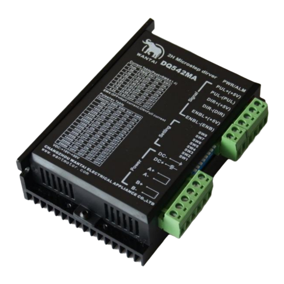
Stepper Motor Driver DQ542MA
Electrical specification:
Input voltage
Input current
Output current
Consumption
Temperature
Humidity
gas
weight
Pins assignments and description:
1) Connector Pins Configurations
Pin Function
PUL +,PUL- Pulse signal, PUL+ is the positive end of pulses input pin PUL- is the negative
end of pulse input pin
DIR+,DIR- DIR signal: DIR+ is the positive end of direction input pin DIR- is the negative
end of direction input pin
18-50VDC
< 4A
1.0A~4.2A
Consumption:80W; Internal Insurance
:6A
Working Temperature -10~45℃;
Stocking temperature -40℃~70℃
No condensation, no water droplets
Prohibition of combustible gases and
conductive dust
300GS
Details
Advertisement
Table of Contents

Subscribe to Our Youtube Channel
Related Manuals for wantai DQ542MA

Summary of Contents for wantai DQ542MA
- Page 1 Stepper Motor Driver DQ542MA Electrical specification: Input voltage 18-50VDC < 4A Input current 1.0A~4.2A Output current Consumption:80W; Internal Insurance Consumption :6A Working Temperature -10~45℃; Temperature Stocking temperature -40℃~70℃ Humidity No condensation, no water droplets Prohibition of combustible gases and conductive dust...
- Page 2 ENBL+ Enable signal: ENBL+ is the positive end of direction input pin. This signal is used for enabling/disabling the driver. High level for enabling the driver and low level for disabling the driver. ENBL- ENBL- is the negative end of direction input pin. Usually left unconnected (enabled) 2) Pins wiring diagram: PC’s control signals can be active in high and low electrical level.
- Page 3 Fig. 2 Input port circuit ( Yin connection) PC PNP output Note: When VCC=5V, R=0 When VCC=12V, R=1K, >1/8W When VCC=24V, R=2K,>1/8W R must connect in the control signal part . 3.Function choice ( Using DIP pins to achieve this function) 1) Micro step resolution is set by SW 5,6,7,8 of the DIP switch as shown in the following table: SW5 OFF ON OFF ON OFF ON OFF ON OFF ON OFF ON OFF ON OFF ON OFF OFF ON ON OFF OFF ON ON OFF OFF ON ON OFF OFF...
- Page 4 Motors wiring Motor and power pins DC+ D Power supply :DC18-50VDC Power supply 5. Mechanical Specification: To have 20mm of space around, cannot be placed next to other heating devices. Whats more, avoid dust, oil mist, corrosive gas, heavy humidity and high vibration. 6.
- Page 5 Wrong connection of stepper Correct its wiring Motor doesn’t run, without motor holding torque RESET signal is effective Make RESET ineffective when offline Motor doesn’t run, but maintains holding Without input pulse signal Adjust PMW & signal level torque Wrong wires’ connection Change connection for any of 2 wires Motor runs wrong direction Wrong input direction signal...
Need help?
Do you have a question about the DQ542MA and is the answer not in the manual?
Questions and answers