
Summary of Contents for Lava ATTILA GN 2/3
- Page 1 ATTILA ® GN2/3 MANUALE D’USO E MANUTENZIONE USER AND MAINTENANCE MANUAL NOTICE DÉ UTILIZATION Rev. 01_2018 - del 02/2018 Cod. LIATTT...
- Page 2 IT | Abbattitori di temperatura | Manuale d’uso e manutenzione Istruzioni originali Benvenuto Vi ringraziamo per aver scelto un nostro prodotto. ATTENZIONE Siete invitati a leggere attentamente il presente manuale per assicurarvi l'utilizzo LEGGERE ISTRUZIONI ottimale della Vostra attrezzatura. ITALIANO - RAEE - Gestione rifiuti apparecchiature elettriche ed elettroniche - Il simbolo del bidone barrato posto sul prodotto o sulla documentazione del manuale d’uso, indica che il prodotto è...
-
Page 3: Table Of Contents
Abbattitori di temperatura | Manuale d’uso e manutenzione | IT SOMMARIO INTRODUZIONE PAG.4 DESCRIZIONE DELL’ABBATTITORE PAG.5 1 POSIZIONAMENTO DELL’ABBATTITORE PAG.6 1.1 TRASPORTO Pag.6 1.2 SCARICO ABBATTITORE / DIMENSIONI / PESI Pag.6 1.3 IMBALLO Pag.6 1.4 SCARICO ACQUA DI CONDENSA / COLLEGAMENTO SCARICO Pag.7 1.5 POSIZIONAMENTO E REGOLAZIONE PIEDINI Pag.7... - Page 4 IT | Abbattitori di temperatura | Manuale d’uso e manutenzione INTRODUZIONE L’apparecchio denominato “ABBATTITORE DI TEMPERATURA” è stato realizzato rispettando l’insieme delle norme comunitarie riguardanti la libera circolazione dei prodotti industriali e commerciali nei paesi Prima di effettuare una qualsiasi operazione sul prodotto, si raccomanda di leggere attentamente il manuale d’uso e manutenzione.
-
Page 5: Descrizione Dell'abbattitore
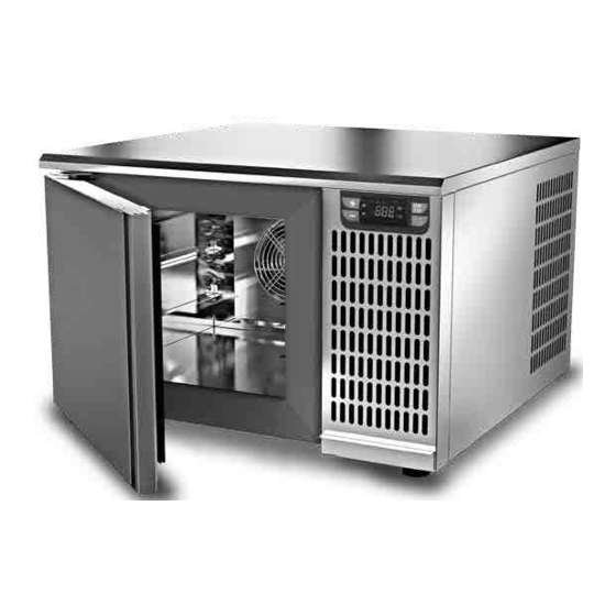
Abbattitori di temperatura | Manuale d’uso e manutenzione | IT DESCRIZIONE DELL’ABBATTITORE Il presente manuale fa riferimento ad un Abbattitore di temperatura ovvero ad un macchinario refrigerante in grado di raffreddare velocemente un prodotto cotto fino a +3°C (Abbattimento positivo) oppure fino a -18°C (Ab- battimento negativo o surgelazione). -
Page 6: Posizionamento Dell'abbattitore
IT | Abbattitori di temperatura | Manuale d’uso e manutenzione 1 POSIZIONAMENTO DELL’ABBATTITORE Prima di scaricare/caricare e posizionare l’Abbattitore all’interno del locale di vendita, si prega di consultare at- tentamente il manuale nelle varie sezioni riguardanti lo scarico/carico dell’Abbattitore, lunghezze, pesi, vaschetta di scarico acqua di condensa, posizione dei piedini di regolazione e del quadro elettrico relativo al presente nel manuale d’uso e di manutenzione dell’Abbattitore. -
Page 7: Scarico Acqua Di Condensa / Collegamento Scarico
Abbattitori di temperatura | Manuale d’uso e manutenzione | IT 1.4 SCARICO ACQUA DI CONDENSA / COLLEGAMENTO SCARICO L’Abbattitore è disponibile nella versione con unità refrigerante incorporata completa di vaschetta scarico acqua condensa estraibile con sbrinamento manuale (senza resistenze di sbrinamento). La vaschetta è... -
Page 8: Distanze Minime Dal Muro
IT | Abbattitori di temperatura | Manuale d’uso e manutenzione 1.7 DISTANZE MINIME DAL MURO Al fine di permettere un buon funzionamento dell’Abbattitore e quindi un corretto ricircolo d’aria, durante la fase di posizionamento, si devono rispettare le distanze MINIME come segue: •... -
Page 9: Avviamento Dell' Abbattitore
Abbattitori di temperatura | Manuale d’uso e manutenzione | IT • Si consiglia di montare un interruttore bipolare (o quadri polare) di sezionamento con apertura dei contatti di almeno 3 mm, a monte della presa. Questo interruttore è obbligatorio quando il carico supera i 1000 Watt o quando l’Abbattitore viene collegato direttamente senza l’impiego della spina. -
Page 10: Pulizia
IT | Abbattitori di temperatura | Manuale d’uso e manutenzione 3 PULIZIA Tutte le operazioni di pulizia devono essere eseguite con unità ferma, togliendo tensione sia all’apparecchio refrigerato che all’unità condensatrice. 3.1 PULIZIA CAMERA DELL’ABBATTITORE La manutenzione dell’Abbattitore deve includere almeno una pulizia periodica giornaliera della zona di carico per prevenire lo sviluppo e l’accumulo di batteri. -
Page 11: Raccomandazioni Ed Avvertenze
Abbattitori di temperatura | Manuale d’uso e manutenzione | IT sono sostanze detergenti che possono distruggere o intaccare questo strato e dare così origine a corrosioni. Prima di usare qualsiasi prodotto detergente informatevi presso il vostro fornitore di fiducia sul detergente neu- tro privo di cloro, per evitare corrosioni sull’acciaio. -
Page 12: Sbrinamento Manuale
IT | Abbattitori di temperatura | Manuale d’uso e manutenzione 4.1 SBRINAMENTO MANUALE Lo sbrinamento dell’Abbattitore avviene in modo manuale e può essere eseguito con porta aperta o con porta chiusa (in quest’ultimo caso, il tempo di sbrinamento sarà maggiore). ATTENZIONE Ad ogni fine ciclo di sbrinamento controllare il livello dell’acqua e se serve vuotare la vaschetta. - Page 13 Abbattitori di temperatura | Manuale d’uso e manutenzione | IT MISURAZIONE TEMPERATURA AL CUORE DEL PRODOTTO CUORE DEL Quando lo spessore del prodotto lo consente, utilizzare sempre la sonda di tem- PRODOTTO peratura a spillone, per conoscere l’esatta temperatura raggiunta la cuore del pro- dotto, si suggerisce, inoltre, di non interrompere il ciclo di abbattimento prima che si sia raggiunta la temperatura di +3°C, in abbattimento positivo e -18°C per quello negativo.
-
Page 14: Procedure Per L'avviamento Dell'abbattitore
IT | Abbattitori di temperatura | Manuale d’uso e manutenzione CONSERVAZIONE PRODOTTO COTTO ED ABBATTUTO Il prodotto cotto ed abbattuto può essere conservato in frigorifero mantenendo le qualità orga- nolettiche fino a 5 giorni da quello di trattamento. È importante rispettare la catena del freddo, mantenendo durante la conservazione una temperatura costante compresa tra 0 °C ÷... -
Page 15: Tempi (Mesi) Di Conservazione Degli Alimenti Abbattuti
Abbattitori di temperatura | Manuale d’uso e manutenzione | IT CICLO DI ABBATTIMENTO A TEMPO 1 - Premere Start/Stop per accendere l’abbattitore. 2 - Premere il tasto SET per selezionare i tempi standard 90 o 270 3 - Se necessario premere i pulsanti Up , Down per modificare il tempo per il ciclo di abbattimento 4 - Premere Start/Stop... -
Page 16: Tempi Di Abbattimento
IT | Abbattitori di temperatura | Manuale d’uso e manutenzione 5 TEMPI DI ABBATTIMENTO CARICO SPESSORE TEMPO DI CICLO ALIMENTO TEGLIA MASSIMO PRODOTTO ABBATTIMENTO UTILIZZATO PRIMI PIATTI Besciamella GN1/1 h60 4 cm 70 minuti POSITIVO Brodo di carne GN1/1 h110 6-7 cm 90 minuti POSITIVO... -
Page 17: Pannello Comandi
Abbattitori di temperatura | Manuale d’uso e manutenzione | IT 6 PANNELLO COMANDI 6.1 DESCRIZIONE Il controllore permette la gestione delle funzioni base di un Abbattitore: • Abbattimento positivo o raffreddamento • Abbattimento negativo o surgelazione • Fine abbattimento con sonda al cuore o a tempo •... -
Page 18: Interfaccia
IT | Abbattitori di temperatura | Manuale d’uso e manutenzione 6.2 INTERFACCIA All’avvio il controllore effettua un lamp-test di 5 secondi dopo di che si pone in “Operativo”. Stand-by Visualizzazione Il display visualizza “. ” Tasti Il pannello di controllo si pone in modalità Stand-by se, a cicli di abbattimento fermi, viene premuto il tasto Start/ Stop per 4 secondi Impostazione programmi a tempo e con sonda al cuore... -
Page 19: Allarmi
Abbattitori di temperatura | Manuale d’uso e manutenzione | IT Stop Visualizzazione Il display visualizza il tempo (in minuti) se è selezionato un ciclo a tempo oppure la temperatura della sonda al cuore in °C per un ciclo a sonda. Il simbolo “... -
Page 20: Regolazioni
IT | Abbattitori di temperatura | Manuale d’uso e manutenzione 6.4 REGOLAZIONI Compressore Il compressore può essere attivo solo in start con la sonda camera non in errore, la porta deve essere chiusa per dare il consenso all’avvio del compressore solo se P6=0. Con P6=1 il compressore è attivo anche con porta aperta e a ventola ferma per un tempo limitato. -
Page 21: Manutenzione - Gestione Rifiuti - Smaltimento Materiali
Abbattitori di temperatura | Manuale d’uso e manutenzione | IT 7 MANUTENZIONE - GESTIONE RIFIUTI - SMALTIMENTO MATERIALI Tutte le operazioni di manutenzioni e riparazioni dell’Abbattitore di Temperatura devono essere esegui- te con unità ferma, togliendo tensione sia all’Abbattitore stesso che all’unità condensatrice se remota. Tali operazioni devono essere eseguite esclusivamente da personale abilitato e specializzato. -
Page 22: Ordinare Le Parti Di Ricambio
IT | Abbattitori di temperatura | Manuale d’uso e manutenzione 7.5 ORDINARE LE PARTI DI RICAMBIO Comunicare in modo chiaro ai nostri uff.commerciali: • Modello del mobile frigorifero • Numero di matricola del mobile frigorifero • Quantità del ricambio Eventualmente allegare una foto del particolare da ordinare. 8 MESSAGGI DI ERRORE E SOLUZIONI GUASTO MESSAGGIO... - Page 23 Abbattitori di temperatura | Manuale d’uso e manutenzione | IT Informazioni generali sul prodotto: codice BSFjkz (identificazione del singolo particolare del codice della famiglia BSF - Abbattitore di temperatura) "BSF" TIPOLOGIA DI PRODOTTO possibili opzioni: Abbattitore di temperatura "j" numero di teglie o griglie dell’ EUT possibili opzioni: 03GN23 = capacità...
- Page 24 IT | Abbattitori di temperatura | Manuale d’uso e manutenzione Translation of the original instructions Welcome ATTENTION The producer thanks you for choosing one of its products. READ INSTRUCTION We kindly ask you to read carefully our manual: this will guarantee the optimal use of your equipment. ENGLISH - RAEE - Electrical and Electronic Waste Management The barred can symbol displayed on the product or in the use manual documentation indicates that the product has been placed for sale on the market after August 13, 2005.
-
Page 25: Declaration Of Conformity - Declaration De Conformitè- Konformitätserklärung Appendice
Abbattitori di temperatura | Manuale d’uso e manutenzione | IT INTRODUCTION PAG.26 USING MANUAL Pag.26 MANUAL PRESERVATION Pag.26 DESCRIPTION OF THE BLAST CHILLER PAG.27 1 POSITIONING OF THE BLAST CHILLER/FREEZER PAG.28 1.1 TRANSPORT Pag.28 1.2 UNLOADING / DIMENSIONS/ WEIGHTS Pag.28 1.3 PACKING Pag.28 1.4 CONDENSATE WATER DRAINING/ DRAINING CONNECTION... -
Page 26: Using Manual
EN | Blast chillers | User and maintenance manual INTRODUCTION The “BLAST CHILLER / SHOCK FREEZER” has been constructed in respect of the overall community norms concerning the free circulation of industrial and commercial products in EU countries Before proceeding with all the operations on the products, it is recommendable to read carefully the user’s manual and maintenance. -
Page 27: Description Of The Blast Chiller
Blast chillers | User and maintenance manual | EN DESCRIPTION OF THE BLAST CHILLER The current manual refers to a blast chiller that is an appliance suited for cooling quickly cooked food to a temperature of +3° C (positive process) or to -18° C (negative process). ATTILA DIMENSIONI - DIMENSIONS WxDxH mm... -
Page 28: Positioning Of The Blast Chiller/Freezer
EN | Blast chillers | User and maintenance manual 1 POSITIONING OF THE BLAST CHILLER/FREEZER Before unloading/loading and positioning the blast chiller/freezer inside the shop/kitchen, you are kindly reque- sted to read carefully the instruction manual in the different chapters regarding the unloading/loading, dimen- sions, weight, evaporating water basin, adjustable feet, electric connections and maintenance procedures of the blast chiller/freezer subjected in the present manual. -
Page 29: Positioning And Feet Regulation
Blast chillers | User and maintenance manual | EN 1.5 POSITIONING AND FEET REGULATION Place the blast chiller/freezer in a perfect horizontal position, acting if necessary on the screw type adjustable feet. Use a spirit level to check it. The blast chiller/freezer must be placed in order to operate properly and allow the correct defrost condensate water drai- ning. -
Page 30: Blast Chiller With Built In Condensing Unit
EN | Blast chillers | User and maintenance manual 1.8 BLAST CHILLER WITH BUILT IN CONDENSING UNIT The blast chiller is provided with built in condensing unit, therefore it is necessary not to obstruct the blast chiller/freezer air inlet corresponding to the front grid for the air extraction in order to allow a proper air circulation. -
Page 31: Starting The Blast Chiller
Blast chillers | User and maintenance manual | EN 2.2 STARTING THE BLAST CHILLER ATTENTION The first start up must be carried out by qualified staff. Before switching on the blast chiller, be sure that: • Your hands must be dry •... -
Page 32: Cleaning The Probe
EN | Blast chillers | User and maintenance manual • Do not flush directly the inner parts of the blast chiller because the electrical parts could get damaged. • Do not use any hard metal tools to remove the ice. •... -
Page 33: Recommendations And Warnings
Blast chillers | User and maintenance manual | EN 4 RECOMMENDATIONS AND WARNINGS ATTENTION This professional equipment may only be used and cleaned by adults (> 18 years of age in Europe or other limits defined by local legislation) in normal physical and psychological condition and who have been adequately trained and informed regarding health and safety in the workplace. - Page 34 EN | Blast chillers | User and maintenance manual MODALITIES SELECTION OF THE PROCESS TIME The modalities selection of the blast chiller are: • Time cycle, when the process time is specified. When the time cycle phase finishes, the conservation mo- dality automatically starts.
- Page 35 Blast chillers | User and maintenance manual | EN SPACE BETWEEN THE PANS In order to permit a good air circulation inside the Blast Chiller room: • it is necessary to keep at least 7 cm space between the pans. POSITION OF THE PANS In order to permit a good process: •...
- Page 36 EN | Blast chillers | User and maintenance manual The food which is subject to negative cycle can be safely preserved for a period of time from 3 to 18 months, according to the food treated. • It is important to respect the conservation temperature equal or below -20°C. ATTENTION •...
-
Page 37: Conservation Time (In Months) For Blast Chilled-Shock Frozen Food Pag.37
Blast chillers | User and maintenance manual | EN 4.4 CONSERVATION TIME (IN MONTHS) FOR BLAST CHILLED- SHOCK FROZEN FOOD In the chart below there are the preservation times of some deep-frozen food. Freezing Freezing Freezing FOOD -18°C -25°C -30°C DAIRY PRODUCTS Cheese Butter... -
Page 38: Blast-Chilling/Shock Freezing Time
EN | Blast chillers | User and maintenance manual 5 BLAST-CHILLING/SHOCK FREEZING TIME MAXIMUM PRODUCT BLAST -FREEZING FOOD LOADING CYCLE USED THICKNESS TIME CAPACITY PRIMI PIATTI White sauce GN1/1 h60 4 cm 70 minutes POSITIVE Meat Stock GN1/1 h110 6-7 cm 90 minutes POSITIVE Cannelloni... -
Page 39: Control Panel
Blast chillers | User and maintenance manual | EN 6 CONTROL PANEL 6.1 DESCRIPTION The controller allows to manage the basic functions of a Blast chiller: • Positive blast chilling or cooling • Negative blast chilling or deep freezing • End of blast chilling with core or time-based probe •... - Page 40 EN | Blast chillers | User and maintenance manual INTERFACE When started, the controller performs a 5-second lamp-test after which it is “Operational”. Stand-by Display The display shows “. “ Keys The control panel goes into Stand-by mode if, with the blast chilling cycles stopped, the Start/Stop button is pressed for 4 seconds Time-based and core probe program settings...
-
Page 41: Alarms
Blast chillers | User and maintenance manual | EN Stop Display The display shows the time (in minutes) if a time-based cycle is selected or the temperature of the core probe in °C for a probe cycle. The symbol “ ”... - Page 42 EN | Blast chillers | User and maintenance manual The protection times for the compressor are always present and they are: • P9: minimum delay between a shut-down and the next start-up of the compressor. This parameter is also used to reset the card. •...
-
Page 43: Maintanance - Garbage Management - Disposal Of Materials Pag.43
Blast chillers | User and maintenance manual | EN 7 MAINTANANCE - GARBAGE MANAGEMENT - DISPOSAL OF MATERIALS All maintenance operations and reparations of the apliance must be carried out with stationary unit, removing the tension from both the refrigerated item and the condensing unit. All the operations must be carried out by qualified and specialized staff. -
Page 44: Requesting Spare Parts
EN | Blast chillers | User and maintenance manual 7.5 REQUESTING SPARE PARTS After verifying the problem with a specialized technician, When requesting spare parts, after please say clearly : • Model of the item • Serial number of the item •... - Page 45 Blast chillers | User and maintenance manual | EN Note...
- Page 46 FR | CELLULES DE REFROIDISSEMENT | NOTICE D’UTILISATION Bienvenue Traduction de la notice originale Le producteur vous remercie pour avoir choisi un des produits de notre gamme. ATTENTION Nous vous invitons à lire très attentivement ce manuel : ceci garantira une utilisation optimale de votre armoire réfrigérée. LIRE L'INSTRUCTION FRANCAIS - RAEE - Gestion des déchets d’appareillages électriques et électroniques Le symbole de la poubelle barrée placé...
- Page 47 CELLULES DE REFROIDISSEMENT | NOTICE D’UTILISATION | FR INTRODUCTION PAG.48 USAGE DU MANUEL Pag.48 CONSERVATION DU MANUEL Pag.48 DESCRIPTION PAG.49 1 POSITIONNEMENT DE LA CELLULE PAG.50 1.1 TRANSPORT Pag.50 1.2 DÉCHARGEMENT CELLULE / DIMENSION / POIDS Pag.50 1.3 EMBALLAGE Pag.50 1.4 EVACUATION DES EAUX DE CONDENSATS Pag.50 1.5 POSITIONNEMENT ET RÉGLAGE DES PIEDS...
-
Page 48: Usage Du Manuel
FR | CELLULES DE REFROIDISSEMENT | NOTICE D’UTILISATION INTRODUCTION L’appareil dénommé “Cellule de refroidissement“ a été réalisé en respectant l’ensemble des normes communautaires qui con- cernent la libre circulation des produits industriels et commerciaux dans les pays U.E. Nous vous recommandons de lire très attentivement le manuel avant toute opération : de déplacement, d’installation et mise en marche de l’appareil. - Page 49 CELLULES DE REFROIDISSEMENT | NOTICE D’UTILISATION | FR DESCRIPTION Le présent manuel fait référence à une Cellule de refroidissement, c’est-à-dire à un outil réfrigérant apte à refroidir rapidement un produit cuit jusqu’à +3°C (froid positif) ensuite jusqu’ à -18°C (froid négatif). ATTILA DIMENSIONI - DIMENSIONS WxDxH mm...
-
Page 50: Positionnement De La Cellule
FR | CELLULES DE REFROIDISSEMENT | NOTICE D’UTILISATION 1 POSITIONNEMENT DE LA CELLULE Avant de charger/décharger et positionner la cellule à l’intérieur du local de vente, veuillez consulter atten- tivement le manuel dans les diverses sections concernant le chargement/déchargement de la cellule, longueur, poids, bac de vidange des eaux de condensats, position et réglage des pieds, et du cadran électrique relatif à... -
Page 51: Positionnement Et Réglage Des Pieds
CELLULES DE REFROIDISSEMENT | NOTICE D’UTILISATION | FR 1.5 POSITIONNEMENT ET RÉGLAGE DES PIEDS Faites attention à positionner la cellule de refroidissement horizontalement, en réglant si nécessaire les pieds à vis de la cellule pour la mettre à niveau, vérifier le bon positionnement à l’aide d’un niveau à bulle. La cellule de refroi- dissement doit être positionnée parfaitement à... -
Page 52: Distance Minimum De La Cellule Au Mur
FR | CELLULES DE REFROIDISSEMENT | NOTICE D’UTILISATION 1.7 DISTANCE MINIMUM DE LA CELLULE AU MUR Afin de permettre un bon fonctionnement de la cellule et donc une correcte circulation d’air, durant la phase de positionnement, les distances MINIMUM doivent être respectées comme indiqué ci dessous : •... -
Page 53: Connexion Électrique Et Emplacement
CELLULES DE REFROIDISSEMENT | NOTICE D’UTILISATION | FR 2 CONNEXION ÉLECTRIQUE ET EMPLACEMENT 2.1 PUISSANCE ÉLECTRIQUE L’installation et les connexions électriques doivent être effectuées de façon professionnelle en fon- ction des normes électriques en vigueur. Ce travail sera effectué par un personnel compétent et qualifié... -
Page 54: Nettoyage
FR | CELLULES DE REFROIDISSEMENT | NOTICE D’UTILISATION Vérifier aussi que : La cellule avec unité de condensation incorporée a été transporté seulement et exclusivement en position verticale, si la cellule est inclinée, il est conseillé d’attendre au moins huit heures, avant de procéder à la mise en route. -
Page 55: Nettoyage De La Sonde De Température
CELLULES DE REFROIDISSEMENT | NOTICE D’UTILISATION | FR 3.2 NETTOYAGE DE LA SONDE DE TEMPÉRATURE La manutention de la cellule doit inclure un nettoyage de la sonde de température une fois par jour pour éviter la formation de bactéries. Il est indispensable de maintenir propre la sonde de température de la cham- bre de la cellule. -
Page 56: Avertissements D'usage
FR | CELLULES DE REFROIDISSEMENT | NOTICE D’UTILISATION 4 AVERTISSEMENTS D’USAGE On conseille un nettoyage extérieur journalier du meuble et de la partie interne de la porte en proximité des joints. ATTENTION ! Cet équipement peut être utilisé et nettoyé uniquement par des sujets majeurs (> 18 ans en Europe ou autres limites définies par les réglementations locales) se trouvant dans des conditions psycho-physiques normales, aguerris et bien formés en matière de protection de la santé... - Page 57 CELLULES DE REFROIDISSEMENT | NOTICE D’UTILISATION | FR MODALITES DE SELECTION DU CYCLE DE REFROIDISSE-MENT Les modalités de sélection de la réduction de témperature sont les suivantes: • À temps, si on connait le temps de réduction de température du produit à refroidir. Quand la phase à temps termine, on passe automatiquement en cycle de conservation.
- Page 58 FR | CELLULES DE REFROIDISSEMENT | NOTICE D’UTILISATION ESPACE À MAINTENIR ENTRE LES BACS Afin de permettre un bon recyclage de l’air à l’intérieur de la chambre de la cellule : vous devez maintenir un espace de 70 mm entre les bacs. POSITION DES PLATEAUX Afin de permettre un bon refroidissement : •...
-
Page 59: Mise En Marche De La Cellule De Refroidissement Rapide
CELLULES DE REFROIDISSEMENT | NOTICE D’UTILISATION | FR CONSERVATION DU PRODUIT CUIT ET CONGELÉ Le produit cuit et congelé peut être conservé au réfrigérateur tout en maintenant la qualité organoleptique jusqu’à plusieurs mois après traitement. Les produits qui ont subis un cycle de refroidissement négatif peuvent être conservés avec sécurité pendant un temps compris entre 3 et 18 mois, selon le produit traité. -
Page 60: Duree (En Mois) De Conservation Des Aliments Refroidis
FR | CELLULES DE REFROIDISSEMENT | NOTICE D’UTILISATION 4.4 DUREE (EN MOIS) DE CONSERVATION DES ALIMENTS REFROIDIS Tableau reportant les temps de conservation de quelques produits surgelés. Température Température Température ALIMENTS -18°C -25°C -30°C PRODUITS LAITIERS Fromage Beurre VIANDES ET VOLAILLES Boeuf Veau Agneau... -
Page 61: Temps De Refroidissement
CELLULES DE REFROIDISSEMENT | NOTICE D’UTILISATION | FR 5 TEMPS DE REFROIDISSEMENT CHARGEMENT EPAISSEUR TEMPS DE CYCLE ALIMENT GRILLE MAXIMUM DU PRODUIT RE-FROIDISSEMENT UTI-LISE PREMIERS COURS Béchamel GN1/1 h60 4 cm 70 minuti POSITIF Bouillon de viande GN1/1 h110 6-7 cm 90 minuti POSITIF Cannelloni au four... -
Page 62: Panneau De Commande
FR | CELLULES DE REFROIDISSEMENT | NOTICE D’UTILISATION 6 PANNEAU DE COMMANDE 6.1 DESCRIPTION Le contrôleur permet la gestion des fonctions de base d’une Cellule de refroidissement rapide: • Refroidissement rapide positif ou refroidissement • Refroidissement rapide négatif ou surgélation •... -
Page 63: Interface
CELLULES DE REFROIDISSEMENT | NOTICE D’UTILISATION | FR 6.2 INTERFACE A l’allumage, le contrôleur effectue un test des voyants de 5 secondes, puis se met en mode « Fonctionnement ». Stand-by Affichage L’écran affiche “. ” Boutons Le panneau de commande se met en mode Stand-by en cas de pression sur le bouton Start/Stop pendant 4 secondes, quand les cycles de refroidissement rapide sont à... -
Page 64: Alarmes
FR | CELLULES DE REFROIDISSEMENT | NOTICE D’UTILISATION Stop Affichage L’écran affiche le temps (en minutes) si un cycle à temps est sélectionné, ou la température de la sonde à cœur en °C pour un cycle à sonde. Le symbole “ ”... - Page 65 CELLULES DE REFROIDISSEMENT | NOTICE D’UTILISATION | FR • P9: retard minimal devant s’écouler entre une extinction et l’allumage suivant du compresseur. Ce pa- ramètre est également utilisé lors du reset de la carte. • P10: retard minimal devant s’écouler entre deux allumages consécutifs du compresseur. •...
-
Page 66: Controles Periodiques
FR | CELLULES DE REFROIDISSEMENT | NOTICE D’UTILISATION 7 MANUTENTION-GESTION DE DÉCHETS- ELIMINATION DES MATERIAUX Toutes les opérations de manutention et réparation de la mini cellule de refroidissement doivent être faites avec l’unité arrêtée, en déconnectant la tension soit de la chambre, soit de l’unité condensant si elle est à... -
Page 67: Commander Les Pieces Detachees
CELLULES DE REFROIDISSEMENT | NOTICE D’UTILISATION | FR 7.5 COMMANDER LES PIECES DETACHEES Communiquer de manière claire à nos bureaux commerciaux : • Modèle du meuble réfrigéré • Numéro de série du meuble • Quantité des pièces détachées Eventuellement envoyer une photo de la pièce dont vous avez besoin. 8 MESSAGES D’ERREUR ET SOLUTIONS PROBLEME/ MESSAGES... -
Page 68: Dichiarazione Di Conformita
IT - EN - F - DE - ES - ARABIC | Appendici | Manuale d’uso e manutenzione DICHIARAZIONE DI CONFORMITA’ DECLARATION OF CONFORMITY - DECLARATION DE CONFORMITÈ- KONFORMITÄTSERKLÄRUNG FARE RIFERIMENTO ALLA DICHIARAZIONE CE CHE ACCOMPAGNA IL PRODOTTO VEUILLEZ- VOUS REPORTER À LA DÉCLARATION JOINTE AU PRODUIT - REFER TO CE DECLARATION ACCOMPANYING THE PRODUCT - BEACHTEN SIE DIE DEM PRODUKT BEILIEGENDE CE ERKLÄRUNG... - Page 69 األبعاد واألو ز ان Consultate le misure del Vostro apparecchio. - Please consult the dimensions of your cabinet .الرجاء التحقق من القياسات الخاصة بجهازك 3 Teglie GN 2/3 ATTILA GN 2/3 DIMENSIONI - DIMENSIONS - DIMENSIONS - MASSE 658x630x420 WxDxH mm...
- Page 70 IT - EN - F - DE - ES - ARABIC | Appendici | Manuale d’uso e manutenzione APPENDICE - 2 TARGHETTA IDENTIFICAZIONE PRODOTTO - PRODUCT IDENTIFICATION PLATE - ETIQUETTE D’IDENTIFICATION DU PRODUIT - DAS PRODUKT -TYPENSCHILD - TARJETA DE IDENTIFICACIÓN DEL PRODUCTO - PLACA DE IDENTIFICAÇÃO PRODUTO Tale targhetta definisce tutti i dati tecnici del prodotto come riportato nella legenda nella prossima pagina.
- Page 71 Appendici | Manuale d’uso e manutenzione | IT - EN - F - DE - ES - ARABIC LEGENDA / LEGEND Numero Numéro Matrikel- رقم Serial number Numero de serie matricola matricule Number التسجيل Data di Date of Date de Zeitpunkt der Data de تاريخ...
- Page 72 IT - EN - F - DE - ES - ARABIC | Appendici | Manuale d’uso e manutenzione APPENDICE - 3 TEST DIELETTRICO - DIELECTRIC TEST - TEST DIÉLECTRIQUE - DIELEKTRISCHE TEST - PRUEBA DIELÉCTRICA - DIELÉCTRICA TESTE اختبار العزل الكهربايئ APPENDICE - 4 ATTREZZATURA CON GAS FLUORURATI AD EFFETTO SERRA - EQUIPMENT WITH FLUORINATED GREENHOUSE GASES - ÉQUIPEMENT AVEC GAZ À...
- Page 73 Appendici | Manuale d’uso e manutenzione | IT - EN - F - DE - ES - ARABIC APPENDICE - 5 RIEPILOGO SCHEMI ELETTRICI ABBATTITORI - BLAST CHILLERS ELECTRICAL DIAGRAMS - RÉSUMÉ DIAGRAMMES ÉLECTRIQUES - ZUSAMMENFASSUNG SCHALTPLÄNE - RESUMEN DIAGRAMAS ELÉCTRICOS - RESUMO FIAÇÃO ELÉTRICA EWB974EO 10 11 10 11...
- Page 74 IT - EN - F - DE - ES - ARABIC | Appendici | Manuale d’uso e manutenzione Note...
- Page 75 Appendici | Manuale d’uso e manutenzione | IT - EN - F - DE - ES - ARABIC Note...
- Page 76 Le immagini raffiguranti il prodotto sono state realizzate al momento della stampa del presente catalogo e sono pertanto puramente indicative, potendo essere soggette a variazione. Il Produttore si riserva il diritto di modificare modelli, caratteristiche e prezzi senza preavviso. Tutti i dati sono forniti a titolo indicativo e non impegnano il Costruttore.
Need help?
Do you have a question about the ATTILA GN 2/3 and is the answer not in the manual?
Questions and answers