Table of Contents
Advertisement
Quick Links
Advertisement
Table of Contents

Subscribe to Our Youtube Channel
Related Manuals for aci DSIM-CJ


Summary of Contents for aci DSIM-CJ
- Page 1 DSIM-CJ For Flex Max 601e 1GHz Bridger Amplifier Installation Guide Revision C...
-
Page 2: Quick Start Instructions For Single Pilot Agc Operation
Set desired amplifier levels. Press mode button once. The controller light will flash blue and red for approximately 45 seconds. When done the controller light will have a half second blue blink indicating that the DSIM-CJ is in AGC mode. -
Page 3: Table Of Contents
Installation Guide Rev C Table of Contents 1. Quick Start Instructions for Single Pilot AGC Operation ............. 2 2. DSIM-CJ AGC Module & DSIM Controller Overview ............4 3. DSIM Mode Definitions ...................... 5 4. DSIM Controller Operation Instruction Guidelines ............. 7 5. -
Page 4: Dsim-Cj Agc Module & Dsim Controller Overview
AGC. In the SPAGC mode the DSIM-CJ can be programmed to use either an analog or digital pilot signal from channels 52 to 116. If the pilot channel is lost, the DSIM-CJ module will default into a thermal TGC mode and then return to the single pilot SPAGC mode automatically once the pilot channel has been restored. -
Page 5: Dsim Mode Definitions
DSIM-CJ Installation Guide Rev C The DSIM controller is used to set the DSIM-CJ module’s pilot channel and to change into the different operational modes during the amplifier setup. The bi-colored blue and red LED indicator's blinking patterns will denote the current optional mode setting. - Page 6 DSIM-CJ Installation Guide Rev C DSIM Mode Flow Chart MGC mode: This is the default mode for Amp. Setup The controller LED will be solid blue The DSIM LED will blink blue every half sec Press MODE once to start the...
-
Page 7: Dsim Controller Operation Instruction Guidelines
DSIM-CJ Installation Guide Rev C 4. DSIM Controller Operation Instruction Guidelines Switch Function Description In MGC Mode, Click to increase RF output level (See Note 1) Increase In AGC Mode, no function In TGC Mode, Click to increase cable length value... -
Page 8: Dsim-Cj Module Status Led Essentials
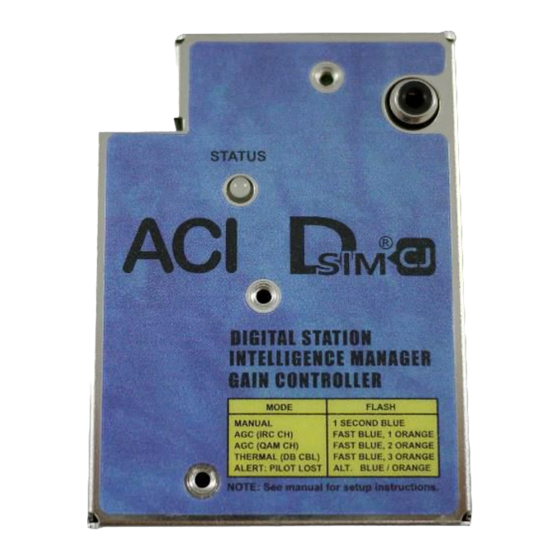
Pilot Lost; DSIM-CJ automatically switches to Quick Blue / Orange Blinks Thermal (TGC) mode until Pilot channel is restored Note: The DSIM-CJ LED blinks after the pilot channel count will be orange during programming and blue when in operation. Page 8 of 16... -
Page 9: Dsim Interface Cable Assembly
The DSIM controllers will come preset to have a desired pilot channel stored in the memory. The controller is used to set the DSIM-CJ module to the desired pilot channel by downloading the pilot channel program into the DSIM-CJ module's memory during setup. - Page 10 Press the mode button 2 times and then go back to step 9. 11. Check the LED on the DSIM-CJ Module to make sure the channel number is right. Refer to section 10 for pilot channel blinking count overview.
-
Page 11: Thermal Agc Setup
27 dB in the memory. The controller is used to set the DSIM-CJ module to either 9 dB, 18 dB, or 27 dB of cable by simply clicking the “Increase” or “Decrease” buttons on the controller. - Page 12 Click + / - button to go to the desired cable length setting choosing from 9 dB, 18 dB, or 27 dB. This cable length dB setting is the dB amount of cable in front of the amplifier. Check the LED on the DSIM-CJ Module to make sure the cable length setting is correct. Cable Length...
-
Page 13: Led Pilot Channel Blink Series Overview
DSIM-CJ Installation Guide Rev C 10. LED Pilot Channel Blink Series Overview Channel DIGITAL Set 1 Set 2 Set 3 Set 4 Blue-Operation Blue Blue Blue Orange-Programming 391.25 393.00 5-Dits 2-Dits 397.25 399.00 5-Dits 3-Dits 403.25 405.00 5-Dits 4-Dits −... - Page 14 DSIM-CJ Installation Guide Rev C Channel DIGITAL Set 1 Set 2 Set 3 Set 4 Blue-Operation Blue Blue Blue Orange-Programming 523.25 525.00 7-Dits 4-Dits 529.25 531.00 7-Dits 5-Dits − 535.25 537.00 7-Dits 6-Dits − 541.25 543.00 7-Dits 7-Dits − 547.25 549.00...
- Page 15 DSIM-CJ Installation Guide Rev C Channel DIGITAL Set 1 Set 2 Set 3 Set 4 Blue-Operation Orange- Blue Blue Blue Programming 655.25 657.00 1-Dits 1-Dash 1-Dits 661.25 663.00 1-Dits 1-Dash 2-Dits 667.25 669.00 1-Dits 1-Dash 3-Dits 673.25 675.00 1-Dits 1-Dash 4-Dits 679.25...
- Page 16 2019 ACI Communications, Inc. All rights reserved Rev C 7-19-2019 Printed in U.S.A. ACI Communications, Inc. reserves the right to discontinue the manufacture or change specifications without prior notice on any parts illustrated in this data sheet. Registered trademarks are the...
Need help?
Do you have a question about the DSIM-CJ and is the answer not in the manual?
Questions and answers