
Related Manuals for DEHN + SÖHNE DEHNrecord DRC MCM XT


Summary of Contents for DEHN + SÖHNE DEHNrecord DRC MCM XT
- Page 1 Operating Manual DEHNrecord DRC MCM XT DEHN + SÖHNE Issued by: DEHN + SÖHNE GmbH + Co.KG. BA 1669 / V 1.006 – Update 03/10 / Id.-No. 056286 © 2010 DEHN + SÖHNE / protected by ISO 16016...
-
Page 2: Table Of Contents
DEHN + SÖHNE Operating manual DEHNrecord DRC MCM XT Index: Terms and definitions ..................3 Literature / References..................4 Application ......................5 LifeCheck®......................5 Equipment specifications ................. 6 Design/Arrangement ..................11 Single application ........................11 Multiple application......................... 12 Connections..................... 13 Power supply........................... -
Page 3: Terms And Definitions
DEHNrecord DRC LC M3+ is a compact hand-held reading device with integrated ® RFID technology for non-contact testing of surge protection modules (Blitzductors DEHNrecord DRC MCM XT DEHNrecord DRC MCM XT is a compact monitoring device with integrated RFID ® technology for stationary testing of surge protection modules (Blitzductors Hardware Software ®... -
Page 4: Literature / References
DEHN + SÖHNE Operating manual DEHNrecord DRC MCM XT 2. Literature / References Operating manual DEHNrecord DRC LC M3+ Issued by DEHN + SÖHNE Operating manual DEHNrecord DRC Software Update Issued by DEHN + SÖHNE Operating manual PC Software Status Display + Service Console Issued by DEHN + SÖHNE... -
Page 5: Application
DEHN + SÖHNE Operating manual DEHNrecord DRC MCM XT 3. Application DEHNrecord DRC MCM XT is a compact monitoring device in an XT enclosure with integrated RFID technology for non-contact stationary monitoring of surge protection modules (SPDs). These SPDs and the monitoring device are marked with the LifeCheck symbol. -
Page 6: Equipment Specifications
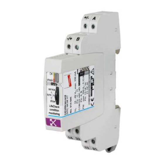
DEHN + SÖHNE Operating manual DEHNrecord DRC MCM XT 5. Equipment specifications DEHNrecord DRC MCM XT stationary monitoring device consists of a special base part for DIN rail mounting and wiring a BXT plug-in module including the condition monitoring unit... - Page 7 DEHN + SÖHNE Operating manual DEHNrecord DRC MCM XT DRC MCM XT plug-in module for plugging/snapping into the base part ® Monitoring device for stationary permanent LifeCheck of up to 10 ® BLITZDUCTOR XT (or CT) modules. 3-way button for controlling DRC MCM XT with the following functions:...
- Page 8 DEHN + SÖHNE Operating manual DEHNrecord DRC MCM XT Indicator element (3-colour LED) for indicating the monitoring and device status. The blinking LED indicates the operating state. Irrespective of the colour, - fast blinking stands for device in Master mode...
- Page 9 DEHN + SÖHNE Operating manual DEHNrecord DRC MCM XT Slider switch/jumper for activating (On) and/or deactivating (Off) the 120 termination impedance (R ) at the connections (A and B) of the serial 2-wire RS485 interface (COM) during half-duplex operation (HD).
- Page 10 DEHN + SÖHNE Operating manual DEHNrecord DRC MCM XT Special base part for DIN rail mounting with terminal screws, for supporting the plug-in module Warning: Base part designed for DRC MCM XT plug-in module only; observe the installation instructions! protected by ISO 16016 Page 10 of 49 Date of issue: 08.03.10...
-
Page 11: Design/Arrangement
DEHN + SÖHNE Operating manual DEHNrecord DRC MCM XT 6. Design/Arrangement ® With DRC MCM XT monitoring device, 1 to 10 BLITZDUCTOR XT or CT modules ® with LifeCheck function can be permanently monitored. Monitoring of BXT...EX...urgently requires the installation of separators TW DRC MCM EX in order to have a separation distance between intrinsically safe and not intrinsically safe circuits! The separator requires a space of min 14 cm (e.g. -
Page 12: Multiple Application
DEHN + SÖHNE Operating manual DEHNrecord DRC MCM XT The termination impedance (R ) at the RS-485 interface should remain active or should be activated for noise immunity. 6.2 Multiple application The minimum distance has not to be kept, if, apart from being connected to the external d.c. -
Page 13: Connections
DEHN + SÖHNE Operating manual DEHNrecord DRC MCM XT 7. Connections Installation wiring at the base and removed plug-in module. Illustration of remote signalling contacts: Functional principle! Contacts are integrated in the monitoring module! Note: Conductors of intrinsically safe and non-intrinsically safe circuits which are routed in same conductor bundle or cable duct, have to be isolated by means of an insulating layer or an earthed metal intermediate layer in accordance with EN 60079-14. -
Page 14: Rs485 Bus Interface
DEHN + SÖHNE Operating manual DEHNrecord DRC MCM XT 7.3 RS485 Bus interface The bus is connected to the device and/or between several devices via the A and B terminals. The individual devices have then to be connected with each other in parallel (A to A and B to B). -
Page 15: Configuration
DEHN + SÖHNE Operating manual DEHNrecord DRC MCM XT 8. Configuration Settings/Modifications of the device configuration can/must only be implemented at the removed plug-in unit. When delivered, all DIP switches are set to OFF. When starting operation, this causes a fault indication (inadmissible configuration). -
Page 16: Interface Termination Impedance
DEHN + SÖHNE Operating manual DEHNrecord DRC MCM XT 8.3 Interface termination impedance The device has a serial RS485 interface for half-duplex operation (HD, 2-wire connection). In order to ensure a safe data transmission on this differential bus, it is... - Page 17 DEHN + SÖHNE Operating manual DEHNrecord DRC MCM XT The termination impedance (R ) can be activated and/or deactivated on the bottom side of the plug-in module after removing it by positioning the slider switch/jumper. The corresponding position can also be taken from the rating plate.
-
Page 18: Programming The Protective Devices
DEHN + SÖHNE Operating manual DEHNrecord DRC MCM XT 9. Programming the protective devices ® In as-delivered state, Blitzductors XT and CT cannot be used with a DRC MCM XT at the same time yet. The protective devices can be assigned to the respective DRC MCM XT monitoring device only by correspondingly programming of the RFID transponders which are integrated into the protective devices. - Page 19 DEHN + SÖHNE Operating manual DEHNrecord DRC MCM XT On the PC the service function Service Console is started in the Status Display + Service Console software and the bus address corresponding to the DRC MCM XT device is set.
- Page 20 DEHN + SÖHNE Operating manual DEHNrecord DRC MCM XT Procedure: Items 1–4 have to be performed one after another and for each individual SPD to be programmed! Insert the SPD to be programmed into its plug-in position, but do not click it...
-
Page 21: Offline Programming By Hand-Held Reader Drc Lc M3
DEHN + SÖHNE Operating manual DEHNrecord DRC MCM XT 3) See also operating manual for Status Display + Service Console software /3/. If all SPDs have been programmed successfully, a test of all SPDs assigned to a selected MCM can and should be initiated by means of the Service Console and the "Check all SPDs of the DRC MCM XT"... - Page 22 DEHN + SÖHNE Operating manual DEHNrecord DRC MCM XT The protection modules can be programmed individually after removing them, or if they are already plugged in. Note: During the programming operation no other unprogrammed SPD must be around the LifeCheck sensor within a circle of 25 cm! Please mind that the stationary reading device DRC MCM XT is inactive, i.e.
- Page 23 DEHN + SÖHNE Operating manual DEHNrecord DRC MCM XT Description Offline programming via DRC LC M3+ - Part 3 Display reading device The LifeCheck test result will be displayed as LifeCheck OK or LifeCheck OK Replace SPD ADR=02 SPD=01 If the programming fails repeatedly, the operating state of the SPD has to be checked with DRC LC M3+ reading device Confirming the result leads automatically to the next current No.
-
Page 24: Starting Operation Of Drc Mcm Xt
DEHN + SÖHNE Operating manual DEHNrecord DRC MCM XT 10. Starting operation of DRC MCM XT When connecting DRC MCM XT to supply voltage or plugging the module into the connected base part, the device starts in the last mode used. - Page 25 DEHN + SÖHNE Operating manual DEHNrecord DRC MCM XT Monitoring of the protective devices by DRC MCM XT is started by setting the DRC MCM XT to the master mode if it used as an individual device. If several DRC MCM XT devices are synchronised via the bus connection, only one of these devices has to/may be set to master mode.
-
Page 26: Monitoring Status
DEHN + SÖHNE Operating manual DEHNrecord DRC MCM XT 11. Monitoring status The monitoring status will be newly determined during every test then indicated by the LED and the remote signalling contacts (FM). There are 3 possible statuses: FM 13-14, no... -
Page 27: Replace Spd" Monitoring Status - Service Measures
DEHN + SÖHNE Operating manual DEHNrecord DRC MCM XT 12. “Replace SPD” monitoring status – Service measures In order to avoid installation standstills, the monitoring system of the protective devices is designed to generate the “Replace SPD” indication already in case of prospective failures due to impermissible overloads. -
Page 28: Offline Determination Via Drc Lc M3/M3+ Hand-Held Reading Device
DEHN + SÖHNE Operating manual DEHNrecord DRC MCM XT Secondly, the indication sequence can be started by individually applying the “show” button. This means that the current number of the first SPD to be replaced is then repeatedly indicated until either the sequence is completed automatically after 1 minute or the sequence changes to the next faulty SPD No. - Page 29 DEHN + SÖHNE Operating manual DEHNrecord DRC MCM XT Offline determination of SPDs to be replaced via DRC LC M3+ hand-held reading device: Description Offline determination via DRC LC M3+ - Part 1 Reading device display The testing of SPDs and all other functions for protective devices in Mode: <...
- Page 30 DEHN + SÖHNE Operating manual DEHNrecord DRC MCM XT Description Offline determination via DRC LC M3+ - Part 2 Reading device display Start the testing process only as soon as the sensor of DRC LC M3+ has been snap onto the SPD to be tested.
-
Page 31: Online Determination Via Status Display + Service Console Pc Software
DEHN + SÖHNE Operating manual DEHNrecord DRC MCM XT 12.3 Online determination via PC software “Status Display + Service Console” The Status Display + Service Console PC software provides a complete overview on the operating state of the protective devices without having to interfere with their processes, especially if several DRC MCM XT monitoring devices are synchronised. - Page 32 DEHN + SÖHNE Operating manual DEHNrecord DRC MCM XT The program and a detailed operating manual are available at www.dehn.de/download or can be ordered there on CD-ROM for a nominal charge. function as a bus device individual operating state OK = SPD alright...
-
Page 33: Functional Extensions For The Drc Mcm Xt
DEHN + SÖHNE Operating manual DEHNrecord DRC MCM XT 13. Functional extensions for the DRC MCM XT With the device software Version V1.008 dated 16 November 2009 the following described extended functions for operating the stationary monitoring device DEHNrecord DRC MCM XT are available. - Page 34 DEHN + SÖHNE Operating manual DEHNrecord DRC MCM XT Procedure: Identification/location of the SPD to be replaced / programmed by the "show" button. Monitoring status „Replace SPD“ Repeated indication sequence, e.g. here replace SPD No. 3 Start of show function, press show button until LED emits orange.
-
Page 35: Acknowledgement Of The Remote Signalling Contact
DEHN + SÖHNE Operating manual DEHNrecord DRC MCM XT 13.1.2 Acknowledgement of the remote signalling contact Within the "show" function the remote signalling contact of the DRC MCM XT can be reset via the 3-way button by acknowledgement even in case of a still existing fault (fault acknowledgement of an issued alarm). -
Page 36: Stopping A Running Test Procedure
DEHN + SÖHNE Operating manual DEHNrecord DRC MCM XT Important note! If the indication status "Replace SPD" has been acknowledged, and thus the RS contact in the system reset at the DRC MCM, there will not be any further status message (e.g. -
Page 37: Technical Data
DEHN + SÖHNE Operating manual DEHNrecord DRC MCM XT 14. Technical data Technical data DRC MCM XT Nominal voltage (perm. range) U 24 (18...48) V Power supply d.c. Nominal current input I 80 (100...60) mA Insulation none, GND indirectly earthed Clamp designation at base part +/- ;... - Page 38 DEHN + SÖHNE Operating manual DEHNrecord DRC MCM XT Technical data DRC MCM XT Enclosure polyamide PA 6.6 (electro grey, RAL 7035) material Degree of IP 20 protection ® Type BLITZDUCTOR XT design Dimension Width (DIN 43880) 12 mm (2/3 TE)
-
Page 39: Projection/Notes On Application
DEHN + SÖHNE Operating manual DEHNrecord DRC MCM XT 15. Projection/Notes on application Number of protective devices to be monitored Operating temperature range Standard: -20°C...+60° C Extended: -40° C...+80° C 1...10 1...8 > 8 > 10 Single application of DRC MCM XT... - Page 40 DEHN + SÖHNE Operating manual DEHNrecord DRC MCM XT Single application of Multiple application of DRC MCM XT DRC MCM XT Minimum Keep a minimum distance (250 mm radius) No minimum distance required. distance between all individual DRC MCM XT!
- Page 41 DEHN + SÖHNE Operating manual DEHNrecord DRC MCM XT Single application of Multiple application of DRC MCM XT DRC MCM XT The 3-colour LED signalises the Operating state (device) means, independent from the blinking frequency, Starting/Starting sequence Service mode activated...
-
Page 42: Warnings
DEHN + SÖHNE Operating manual DEHNrecord DRC MCM XT 16. Warnings The device may only be connected and installed by a qualified electrician. National regulations and safety rules must be observed. Before use, the DRC MCM XT device has to be checked for external damage. If any damage or other fault is found, the device must not be installed. -
Page 43: Maintenance And Care
DEHN + SÖHNE Operating manual DEHNrecord DRC MCM XT 17. Maintenance and care 17.1 Software update The following procedure describes an updating of the device software via interface: Remove the monitoring module Establish an interface-/bus connection from the base part to the PC. Observe the configuration of the bus termination impedances (R ) at the same time. -
Page 44: Cleaning
DEHN + SÖHNE Operating manual DEHNrecord DRC MCM XT Automatic download starts when connecting the device to the power supply. The process can be followed via the user interface. End of transmission will be indicated in the status bar of the PC software and by the blinking LED of the DRC MCM XT device. -
Page 45: Problems / Possible Solutions
DEHN + SÖHNE Operating manual DEHNrecord DRC MCM XT 18. Problems / Possible solutions Problem Causes of fault / Possible solutions LED is not illuminated/blinking after plugging Faulty power supply the module into the base part. - Check the connections! - Page 46 DEHN + SÖHNE Operating manual DEHNrecord DRC MCM XT Problem Causes of fault / Possible solutions -- Is the configuration of the bus address/group No. and number of SPDs to be monitored correct? -- Have all SPDs been programmed? A single...
- Page 47 DEHN + SÖHNE Operating manual DEHNrecord DRC MCM XT Problem Causes of fault / Possible solutions Reverse the acknowledgement of the “Replace Acknowledgement is cancelled as soon as the DRC MCM XT SPD” status for the remote signalling contact. will be reset, i.e.
-
Page 48: Service Mode
DEHN + SÖHNE Operating manual DEHNrecord DRC MCM XT 18.1 Service mode The Service Console PC software in the Status Display + Service Console program provides an excellent tool for obtaining detailed information from the monitoring device and about the monitoring status of the SPDs in case of arising problems and for service work to be performed. - Page 49 DEHN + SÖHNE Operating manual DEHNrecord DRC MCM XT The software provides the following functions: Total test of all protection modules assigned to a DRC MCM XT device Single testing of a protection module Determining the current number of a protection module...
- Page 50 Lightning Protection Surge Protection Safety Equipment DEHN + SÖHNE Hans-Dehn-Straße 1 Postfach 1640 92306 Neumarkt Germany Tel. +49 9181 906 - 462 Fax +49 9181 906 - 444 www.dehn.de export@dehn.de...
Need help?
Do you have a question about the DEHNrecord DRC MCM XT and is the answer not in the manual?
Questions and answers