Table of Contents
Advertisement
Quick Links
TRTC-2004-N1
PLEASE NOTE THIS IS A QUICK REFERENCE GUIDE FOR SETUP AND INSTALLATION.
PLEASE SEE USER MANUAL FOR FULL SAFETY INFORMATION AND INSTRUCTIONS.
• Carefully unpack the UPS. Report any shipping damage immediately.
• Before installation, confirm that the voltage and current requirements of the
load(s) are compatible with the systems output.
• Confirm that the line voltage and current is compatible with the systems input
requirements.
• The system should be installed on a dedicated power circuit.
• Use proper lifting techniques when moving the system.
• The UPS has more than one live circuit. It is fed from AC as well as battery
power. Power may be present at the output(s) even if the system is
disconnected from line power.
• When installing a system in a cabinet, ensure that the environment meets
the system specifications.
310-689-2328
QUICK START GUIDE
SAFETY TIPS
SCAN TO VIEW FULL MANUAL
FOR SUPPORT QUESTIONS CONTACT 310-689-2328 x 103
marathon-power.com
support@marathon-power.com
Advertisement
Table of Contents

Summary of Contents for Marathon Power TRTC-2004-N1
- Page 1 QUICK START GUIDE TRTC-2004-N1 PLEASE NOTE THIS IS A QUICK REFERENCE GUIDE FOR SETUP AND INSTALLATION. PLEASE SEE USER MANUAL FOR FULL SAFETY INFORMATION AND INSTRUCTIONS. SAFETY TIPS • Carefully unpack the UPS. Report any shipping damage immediately. • Before installation, confirm that the voltage and current requirements of the load(s) are compatible with the systems output.
- Page 2 1. Installation Components TRTC-2004-N1 Power Transfer Switch (PTS) External Batteries (4 x 12VDC = 48VDC) Battery Harness Kit...
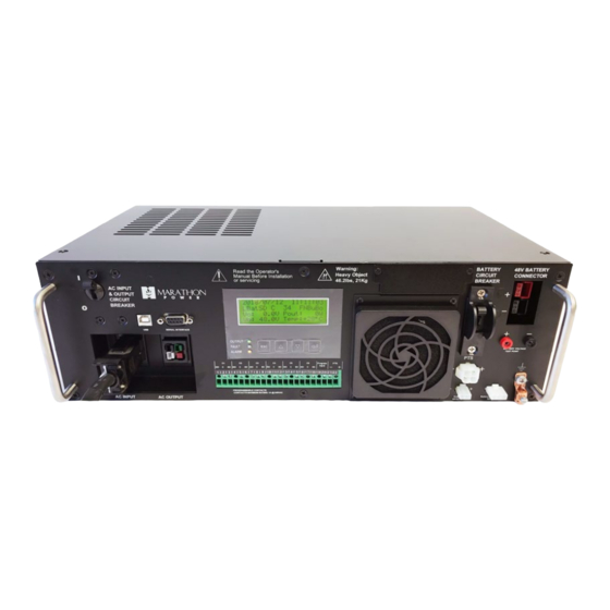
- Page 3 2. Front Panel - TRTC-2004-N1 TRTC-2004-N1 1. AC Input / Output Circuit Breaker 8. Internal Fan 2. USB / Serial Interface / RS232 Connector 9. Battery Circuit Breaker 3. From PTS Input Cable 10. PTS Connector 4. From PTS Output Cable 11.
- Page 4 4. Connecting the Input and Output Power 1. Open / disconnect the upstream breaker feeding utility power to the signal cabinet. 2. Disconnect the HOT wire (Black or Red) connected between utility and the traffic cabinet. 3. Run a #6 - #10 AWG wire (Black or Red) from the Main AC utility source Bus Bar to the VAC IN terminal on PTS.
- Page 5 5. Connecting the Batteries NOTE: Ensure battery breaker is turned open / off. Connect four 12VDC batteries in series for a total of 48VDC. 48V BATTERY CONNECTOR BATTERIES CONNECTED TO BATTERY HARNESS 6. Install and Connect the Temperature Probe NOTE: Batteries are adversely affected by heat; the Temperature Probe provides feedback to control the cooling system.
- Page 6 7. Starting the UPS 1. Verify that the AC Input & Output and the Battery Circuit Breaker on the UPS are Off. 2. Place the Manual Bypass Switch in the UPS position. 3. Turn ON the upstream Utility Input Circuit Breaker. 4.
Need help?
Do you have a question about the TRTC-2004-N1 and is the answer not in the manual?
Questions and answers