
Subscribe to Our Youtube Channel
Summary of Contents for Powr-Flite PP200-Q02-U
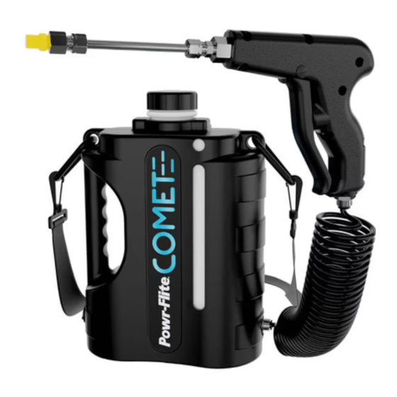
- Page 1 Portable Battery Powered Mister Operations and Maintenance Manual For Commercial Use Only Model No. PP200-Q02-U...
-
Page 3: Table Of Contents
CONTENTS Getting Started Introduction Warranty Polarization Instructions Important Safety Instructions Specifications Box Contents Operating Instructions Initial Assembly Battery Charging Battery Installation Battery Charger Label Definitions Operation After Use Customer Support Trouble Shooting 11-12 Assembly and Maintenance Assembly Instructions Battery Installation Spray Tip Replacement Key Features Schematics... -
Page 4: Introduction
INTRODUCTION Warranty Within 30 days of purchase, to activate product warranty, go to: https://www.powr-flite.com/warranty-registration For warranty information go to www.tornadovac.com. Warning Labels Prior to operating the Portable Battery Powered Mister, read and understand completely this owner’s manual paying special attention to warning labels. These labels indicate a potentially hazardous situation that could result in death or serious injury if not avoided. -
Page 5: Polarization Instructions
POLARIZATION INSTRUCTIONS Your new Powr-Flite unit is a high quality, precision-made product. All parts used in the manufacturing of this unit have passed rigid quality control standards prior to assembly. Please safeguard the original receipt/invoice given at the time of purchase. -
Page 6: Important Safety Instructions
IMPORTANT SAFETY INSTRUCTIONS Read and understand this owner’s manual and all labels on the unit before operating. Safety is a combination of common sense, staying alert, and knowing how your unit works. To reduce the risk of personal injury or damage to your unit use only as indicated in this manual. IMPORTANT: The manufacturer cannot accept responsibility for damage caused when the appliance is not used according to the instructions, or for uses other... - Page 7 IMPORTANT SAFETY INSTRUCTIONS Pressurized Equipment Warning Unit is under high pressure when machine is activated. If leaks are visible around coiled hose connections, replace hose immediately with part number shown in this manual. If pump continues to run when the trigger is not depressed, turn machine OFF, discontinue use and return to an authorized service center.
-
Page 8: Specifications
SPECIFICATIONS Pressure (Max.) 130 PSI / 9 BAR Weight (Empty) 3.9 LBS / 1.8 KG Weight (Full of Solution) ≤7.5 LBS / 3.4 KG Dimensions (HxWxL) 12” x 4” x 8” / 305 x 102 x 203 mm Voltage 10.8 VDC Flow 1.75 GPH / 6.6 LPH Run Time... -
Page 9: Box Contents
BOX CONTENTS Upon initial receipt of unit, open box and ensure all parts are included as shown below: Wand Assembly Coiled Hose Strap Assembly Battery Charger Mister Assembly Battery Owners Manual... -
Page 10: Operating Instructions
OPERATING INSTRUCTIONS Initial Assembly 1. Remove all contents from box and ensure all components are present per the BOX CONTENTS section of this manual. 2. Firmly attach one end of hose to the wand assembly and the other end to the machine ensuring the hose is fully inserted (Figure 1 on page 13). -
Page 11: Battery Charger Label Definitions
OPERATING INSTRUCTIONS Battery Charger Label Definitions 1. Lights flash red and green – bad battery. 2. Lights solid red – battery charging. 3. Lights flash green – standby mode. Charger plugged in and waiting for battery to be inserted. 4. Lights solid green – battery fully charged. 5. -
Page 12: Operation
OPERATING INSTRUCTIONS Operation Prior to filling tank, remove battery from unit and place away from wet area. 1. Remove cap from tank. 2. Pour the recommended amount of disinfectant into the 1⁄2 gallon tank and fill about 1⁄4 of the way with clean water. Replace cap and gently shake contents to mix disinfectant with water. -
Page 13: After Use
OPERATING INSTRUCTIONS After Use 1. Upon completion of disinfection, empty contents of tank into an approved storage container. 2. Add 1⁄4 gallon (half full) of clean water to the tank and replace cap. 3. Turn unit ON, pull spray trigger, and allow clean water to flush through system, making sure to follow proper disposal of the water being flushed through the system as there will be residual chemical found in the spray (Follow chemical manufacturer’s recommendation for disposal). - Page 14 OPERATING INSTRUCTIONS Troubleshooting Occasionally air may enter the system and can cause a vacuum lock. This is indicated by a greatly reduced flow of liquid out of the end of the wand. Follow the steps below to correct. 1. Turn machine OFF. 2.
-
Page 15: Assembly And Maintenance
ASSEMBLY AND MAINTENANCE Assembly Instructions Figure 1 Push hose FULLY into fitting. Once fitting bottoms out, tug on tubing to ensure snug fit. Figure 2... -
Page 16: Battery Installation
ASSEMBLY AND MAINTENANCE Battery Installation Battery Port Figure 3 Press on both sides To remove battery at the same time. Figure 4... -
Page 17: Spray Tip Replacement
ASSEMBLY AND MAINTENANCE Spray Tip Replacement The spray tip is made of plastic and will therefore require replacement over time. Use only the replacement tip listed in the parts section of this manual. 1/2” 1/2” REMOVE INSTALL - USE THREAD SEALER... -
Page 18: Key Features
ASSEMBLY AND MAINTENANCE Key Features 10’ Coiled pressure hose Vacuum relief valve Carry handle Padded shoulder strap with quick disconnects Power switch Trigger Nozzle Extension 10.8v Lithium-ion battery and charger Nozzle Solution level window... -
Page 19: Schematics
ASSEMBLY AND MAINTENANCE Schematics... -
Page 20: Parts List
Clamp, Hose, 1⁄4” X2250 X2229 Pear Link X2260 Label, Attention, Clean After Use X2201 Shell, Right X2235 Label, Powr-Flite Branding X2261 Label, Power Off to Install Battery A328-1500 On/Off Switch X2224 Anti Slip Pad w/HD Adhesive X2203 Nozzle, Spray X2259... - Page 21 PARTS LIST ITEM NO. PART NUMBER DESCRIPTION Swivel Tee, 1⁄4” Tube Push to Connect X 1⁄8” X2227 FNPT Screw, 8-32 X 5⁄8” FHMS ***Undercut*** X2231 Stainless X2256 Pump, Pressure Switch and Silicone Pump Mount Assembly X2264 Nut, Weld, 8-32 X2228 Internal Filter X2258 Cap, Solution Bottle (Aftermarket Part)
- Page 22 NOTES...
- Page 23 NOTES...
- Page 24 Powr-Flite 3101 Wichita Court Ft. Worth, TX 76140-1755 Phone: 817-551-0700 WWW.POWR-FLITE.COM Record of Purchase Serial Number: Purchase Date: Dealer: Phone Number: P-OMPBM 03.21...
Need help?
Do you have a question about the PP200-Q02-U and is the answer not in the manual?
Questions and answers