Table of Contents

Summary of Contents for Schwank Control Touch
- Page 1 Technical Manual SchwankControl Touch Schwank GmbH - Bremerhavener Straße 43 – D-50735 Cologne Tel: +49 [0]221-7176-0 Fax: +49 [0]221-7176-288 E-mail: info@schwank.de Internet: www.schwank.de Language: English Date: 25. Februar 2019 Revision: V 3.0...
-
Page 2: Table Of Contents
Inhalt General ..........................4 Safety ............................5 Technical specifications ......................6 Components .......................... 7 User interface and operation ....................8 5.1. Idle and Home screen ....................8 5.2. User interface ........................9 5.2.1. Tabs........................... 9 5.2.2. Symbols ........................9 5.2.3. Settings ........................ - Page 3 Configuration ........................23 7.1. Heater type configuration ................... 23 7.2. Relay function configuration ..................24 7.3. Input function configuration ..................25 7.4. IC4000 Modbus address assignment ................26 7.5. Special functions [expert settings] ................27 7.5.1. Release contact ....................27 7.5.2.
- Page 4 10.9.3. Humidity sensor ...................... 50 10.9.4. Humidity sensor wiring ................... 52 10.10. Characteristic sensor curves ..................53 10.10.1. Temperature sensor ....................53 10.10.2. Humidity sensor ...................... 54 BMS engineering ......................55 11.1. Connection to SchwankControl control unit ............55 11.2. SchwankControl configuration ................
-
Page 5: General
1. General This operating manual describes the SchwankControl heating control system, its settings and operation, as well as connection options for sensors, automatic burner control units and building control systems. This operating manual provides information on: Safety Technical specifications ... -
Page 6: Safety
The SchwankControl control is exclusively intended for the control of hall heating systems from Schwank. Any other use or use going beyond this is considered improper use. Schwank GmbH accepts no liability for any resulting damage. Risk through improper use is borne solely by the user. -
Page 7: Technical Specifications
CAN 2.0B standard baud rate 125 kBit The control unit is equipped with two RS485 interfaces for networking Schwank automatic burner control units and for integrating the SchwankControl into building control systems. The operating unit can also be connected to a LAN. The operating unit can be operated via a web interface using other computers in the network. -
Page 8: Components
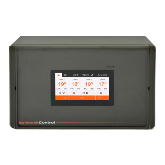
4. Components The standard control integrates a control unit, an operating unit and a touch screen in a single housing. Figure 1: Control unit Figure 2: External components Type plate Main switch LED green: Ready for operation LED yellow: Continuous light = service required Flashing = chimney sweep mode LED red: Error message... -
Page 9: User Interface And Operation
5. User interface and operation The SchwankControl can only be operated via the touch screen. You can switch to individual menu items by lightly touching the corresponding symbol. 5.1. Idle and Home screen Logging out while the control is running activates the idle screen. Automatic logout takes place after a pre- defined period [section 5.4.1] or by pressing the Home button. -
Page 10: User Interface
5.2. User interface 5.2.1. Tabs The main menu bar, which allows selection of the various tabs at all times, is located at the top of the Home screen. As a general rule: Tabs are identified by a symbol or text in the menu bar. ... -
Page 11: Control Unit
5.2.4. Control unit There are up to eight control units in the bus that can be controlled via one user interface. As a general rule: all settings made are only active for the selected control unit. Control unit identifier Selected control unit Control units in the bus [greyed out = not assigned] Figure 5: Control unit overview... -
Page 12: Zone Details
5.3. Zone details Touch the desired control unit to open the detail view. The detail view shows the actual and setpoint temperature in °C, the measured humidity in % and all status flags of the zone. All settings made here only affect the selected zone. -
Page 13: Temperature And Humidity Setpoints
In addition to the operating mode, select the desired time program for the zone. This program is only used in automatic mode. When using automatic mode, a time program must be assigned in advance. To do this, select the "No time program assigned"... -
Page 14: Info Bar - Status Flags
5.3.3. Info bar - status flags All symbols are in fixed positions and indicate the current status of the symbol [active / inactive]. Active symbols are colour-highlighted. 1st Symbol Switch-on optimisation [section 5.6.2] Heaters are switched on earlier so that by switch-on time the setpoint temperature has already been reached. - Page 15 Minimum full load time is active 7th Symbol Heater status [section 8] Heater OFF activated by digital input Partial load Full load Heater ON activated by digital input 8th Symbol Additional information for Symbol 7 Heater is switched on Heater is switched off Heater running at partial load #0...
-
Page 16: Times Menu
5.4. Times menu You can set and edit times under the Settings menu item on the Home screen [section 5.1]. Figure 9: Times menu 5.4.1. Time program The ON time period is set within the time program. Outside of this period, operation changes to the OFF state. Programming is only carried out for automatic mode and each zone must be assigned separately in the Zone details menu item [section 5.3]. -
Page 17: Holiday Periods
Figure11: Day heating phases overview Figure 12: Set day heating phases 5.4.2. Holiday periods The holiday periods set here are taken into account in “Automatic mode including holidays” [section 5.3.1]. During this time, the selected zone is heated to the previously determined holiday temperature. A total of up to 6 different holiday periods can be set. -
Page 18: Date And Time
5.4.3. Date and time Figure 15: Date settings Figure 16: Time settings Date and time are updated via LAN, if this is a possibility 5.4.4. Time zone Automatic daylight saving yes/no Figure171: Time zone settings 5.4.5. Info This screen shows the serial numbers of the boards as well as the current firmware version and further LAN information. -
Page 19: Settings
5.5. Settings The Settings menu item can be accessed via the Home screen [section 5.1]. Figure 19: General settings 5.5.1. Network settings Switch between DHCP and static IP Figure 20: Network settings 5.5.2. Change PIN SchwankControl Touch has 2 PIN levels. -
Page 20: Language
5.5.3. Language Figure 22: Language selection A wide range of languages can be selected. If your desired language is not available, please contact us. 5.5.4. Screen After the specified time has elapsed, the user interface automatically switches to the idle screen; the PIN request is active. -
Page 21: Switch-On Optimisation
5.6.2. Switch-on optimisation Function: The zone is already at setpoint temperature by the switch-on time specified in the time program. Premise: The outdoor temperature sensor must be installed. Switch-on optimisation is in Auto mode [expert setting]. One of the two automatic operating modes must be selected. ... -
Page 22: Gradient Limitation For Setpoint Value Change [Setpoint Ramp]
5.6.4. Gradient limitation for setpoint value change [setpoint ramp] Function: To be able to heat halls / rooms that require very slow temperature changes with SchwankControl, a gradient limitation for setpoint changes has been integrated. This guarantees that the maximum temperature change set for heating and cooling processes is not exceeded. -
Page 23: Chimney Sweep Mode
6. Chimney sweep mode Chimney sweep mode means that all zones of the selected control unit are operated at full load. This enables exhaust gas measurement by the chimney sweep. The "Chimney sweep mode" menu item can be accessed via the corresponding symbol [section 5.2.2] No PIN is required for this. Procedure: Touch a control unit once = chimney sweep mode is activated for all zones of this control unit. -
Page 24: Configuration
7. Configuration The system must be configured before commissioning. These settings are protected by a 5-digit PIN. Figure 25: Expert settings If you log in as an expert, the Home button turns orange with an "E" [expert] inside. To log out, touch and hold the Home button. -
Page 25: Relay Function Configuration
List of available heater types: Zone deactivated Luminous heater single-stage Luminous heater two-stage Luminous heater modulating Tube heater single-stage Tube heater two-stage Tube heater modulating Warm air heater Hybrid system [zone 3 only] ... -
Page 26: Input Function Configuration
Important: Two-stage or modulating heaters require 2 output relays. Example: First, a "Luminous heater two-stage" is configured for zone 2 [section 7.1]. Subsequently, any relay is used for the "Heater ON/OFF" function and a further relay is used for the "Heater stage" function. Both relays are assigned to zone 2. -
Page 27: Ic4000 Modbus Address Assignment
The installed automatic burner control units [ABCU] are assigned to their zone via the software. Background: Schwank IC4000s incl. Modbus interface no longer need to be permanently wired to a specific zone. They can be specifically addressed by the SchwankControl heating control system via a unique address within the Modbus line topology. -
Page 28: Special Functions [Expert Settings]
7.5. Special functions [expert settings] 7.5.1. Release contact Faults that prevent the correct operation of one or more of the control units connected to the bus are indicated by the lighting up of the red LED lamp on the outside of the control unit. The release relay is activated simultaneously with the red LED lamp. -
Page 29: Modbus Slave Address
7.5.6. Modbus slave address When integrating the SchwankControl heating control into an existing building management system [BMS], each connected control unit requires a unique Modbus address. The control unit address corresponds to the address set on the address selector switch of auto the HeatControl: Address 1...8. -
Page 30: Parameters
8. Parameters Parameters for heaters and zones can be adjusted individually. Recommended values have already been entered. These can be reset within each submenu via "Factory settings". Zone 1, 2, 3, 4 The submenus of the zone parameters have the same structure: RTS offset Actual temperature is corrected by the set value Preheating time... - Page 31 Times for luminous heaters, tube heaters and warm air heaters The submenus of the three heater types are identical: Minimum running time Minimum time for which the heater must be switched on. Minimum pause time Time until the heater may be switched on again. Minimum full load time Minimum time for which the heater must run at full load.
-
Page 32: Diagnostics
9. Diagnostics 9.1. Modbus - heater An overview of the up to 32 IC4000s connected to this control unit is displayed. Figure 30: Modbus error counter - heater IC4000 Zone assignment address Current status of the IC4000 Sum of all IC4000 errors Figure 31: Information content of the overview Current status: No pending errors... - Page 33 After touching a burner control unit, the following detail view appears. Reset for the selected IC4000 error list and counter Current status of the IC4000 Error list Figure 32: Modbus error counter details - heater Error list: As soon as an error occurs, it is displayed in this list with the frequency of its occurrence. Each error counter can be reset individually.
-
Page 34: System Counters
9.2. System counters All counters can be reset individually or all at once. The following is displayed: Count down until the next service Total operating time of the control unit Energy consumption of the system [factor required see section 7.5.2] ... - Page 35 History The history shows temperature curves and the corresponding heater output in selectable time periods. After logging in as an expert, access to the history is possible via the zone details [see illustration]. History of the selected zones The day view [see illustration] is shown first. The date displayed in the menu bar defines the day displayed. Touch to manually set a desired day for viewing.
-
Page 36: Mounting Instructions
Drill or punching tool Wall mounting: Drill 10.5. Cable types and board wiring The following diagrams provide basic wiring instructions. In a separate document "Schwank- Electrical Compendium" you will find extensive and detailed wiring diagrams. Revision: 3.0 Page 35 of 70... - Page 37 SchwankControl control unit Room Outdoor Schwank MODBUS Display CANBUS Temp. Temp. Hybrid hydro Heaters Power Relay outputs Digital inputs supply [function assignment via menu] Figure 36: [connections for SchwankControl control unit] Connection Maximum cable Recommended Recommended cross-section cable cross-section cable type Room temperature sensor 2 x 1.5 mm...
- Page 38 Circuit board design of IC 4000 automatic burner control unit Gas solenoid valve Fan [tube heater] Unit control Solenoid Main- Fan- Air pressure 2-St. Reset Err. Power 2-stage valve power monitor supply Ignition Ionisation MODBUS Solenoid Fan- MODBUS monitoring modulation modulation addressing Figure 37: [IC 4000 connections as per delivery status: Terminal resistance PIN open, GDM plug wiring: L/N/PE/Lo]...
- Page 39 Revision: 3.0 Page 38 of 70...
- Page 40 Revision: 3.0 Page 39 of 70...
- Page 41 Revision: 3.0 Page 40 of 70...
- Page 42 When used in systems with relay control, the parameterisation must be adapted accordingly [see separate operating manual of the Schwank heaters used]. Please note that the wiring of the GDM plug must also be changed when used in systems with relay control.
-
Page 43: Bus Wiring
10.6. Bus wiring Each bus node must be assigned a unique address within the bus. Line topology Line topology must be used for the bus wiring. Stubs should always be avoided. Modbus: The maximum stub length per burner control unit is 0.5 m ... -
Page 44: Modbus Wiring Of The Ic4000
10.7. Modbus wiring of the IC4000 Alternative Verdrahtung Modulation IC 4000 ohne Modbus [DE] Alternative modulation wiring to IC 4000 without Modbus [EN] Ab sofort wird der Großteil unserer Strahler mit IC 4000 ausgeliefert. Die IC 4000 ist standardmäßig für die Strahleransteuerung mittles Modbuskommunikation durch SchwankControl Touch vorgesehen und dafür voreingestellt. - Page 45 Inbetriebnahme, Wartungsarbeiten etc. die neueste Softwareversion aufgespielt werden. 4) SchwankControl Touch software update The latest software version can be installed on the main Schwank Control Touch control unit [control and display board] when commissioning, maintenance work, etc. is carried out.
- Page 46 5) Anmerkung zu Modulationsverhalten während Inbetriebnahme / Wartung Es kann ein kurzzeitiges Abfallen der maximalen Modulationsstufe [max. 1 Minute] nach erster Minute Betrieb eintreten, wenn der Strahler während Inbetriebnahme/Wartung manuell durch Abziehen des Gerätesteckers neu gestartet wird. Der Grund liegt im Versatz zwischen den Algorithmen von SchwankControl Touch und IC 4000.
-
Page 47: Ic4000 Error Codes [De&En]
10.8. IC4000 error codes [DE&EN] The same fault codes given in the IC4000 documentation are used for burner faults that are displayed in the diagnostics function of the SchwankControl [see also section 9.1]. Error Error name Description Code Ionisation Error During Start If no flame is detected after ALL ignition attempts during start-up. -
Page 48: Wiring Of Probes And Sensors
10.9. Wiring of probes and sensors 10.9.1. RTS [room temperature sensor] & OTS [outdoor temperature sensor] Two wires are required. Colour and pole correctness are not important for temperature-dependent resistors [NTC]. There are 3 clamping units in the temperature sensor, but only 2 clamping units need to be connected to the control at any one time, see circuit diagram below. - Page 49 Room temperature sensor RTS Wiring Part number: 40652071 SchwankControl Touch: Wire: red-white ThermoControl versions: Wire: red-black Revision: 3.0 Page 48 of 70...
-
Page 50: Rts Averaging
10.9.2. RTS averaging For large halls, 4 room temperature sensors can be installed, spaced around the hall, to calculate an average temperature. From the control point of view, these 4 RTSs correspond to exactly one room temperature sensor for one zone. In this way, the zone to which this interconnected temperature sensor is connected adjusts to the desired setpoint temperature on the basis of the average temperature of the hall. -
Page 51: Humidity Sensor
10.9.3. Humidity sensor Type 1 is used [see pin assignment], article number: 70000142 Application Apparatus for measuring the relative humidity in industrially and commercially used facilities. Characteristics The standard series covers several different measuring ranges of temperature and humidity including relative, absolute humidity, dew point, enthalpy or mix ratio [see configuration table]. - Page 52 Measurement ranges DIP Switch [S1] Humidity ranges Range Relative humidity 0 % ... 100 % Absolute himudity 0 g/m³ … 30g/m³ 0 g/m³ … 50g/m³ 0 g/m³ … 80g/m³ Mix ratio 0 g/kg … 30g/kg 0 g/kg … 50g/kg 0 g/kg … 80g/kg Dew point 0°C …...
-
Page 53: Humidity Sensor Wiring
10.9.4. Humidity sensor wiring Mounting Advice The convection must be aligned at the bottom to ensure a flow of air up [see marking back of the housing] The sensor should always be mounted in an appropriate distance to the heaters. Ideal mounting height of 1.5 m above the floor. Revision: 3.0 Page 52 of 70... -
Page 54: Characteristic Sensor Curves
10.10. Characteristic sensor curves 10.10.1. Temperature sensor Revision: 3.0 Page 53 of 70... -
Page 55: Humidity Sensor
10.10.2. Humidity sensor Revision: 3.0 Page 54 of 70... -
Page 56: Bms Engineering
11. BMS engineering 11.1. Connection to SchwankControl control unit Stubs should always be avoided Modbus data lines: A+, B-, COM 11.2. SchwankControl configuration SchwankControl = Modbus slave, BMS = Modbus master. Set the SchwankControl address. The SchwankControl can be accessed within the BMS Modbus at this address. -
Page 57: Wiring For Converter
The adapters are delivered already configured and only have to be wired to the SchwankControl control and the BMS system available at the customer’s premises. This requires an IP that is within the subnet range of the customer. If we do not know the customer IP on delivery, we burn a standard IP, which is glued to the corresponding adapter. -
Page 58: Wiring For Converter
11.4.2. Wiring for converter MODBUS RTU > KNX Comes with the adapter in printed form Revision: 3.0 Page 57 of 70... -
Page 59: Appendix
12. Appendix 12.1. Drilling dimensions Standard housings [40660000, 40660010, 40660020, 40660130, 40660140, 40660150, 40660170, 40660180] NOT DRAWN TO SCALE, each device comes with a 1:1 scale borehole template Revision: 3.0 Page 58 of 70... - Page 60 Control unit for control cabinet installation [40660040] NOT DRAWN TO SCALE, each device comes with a 1:1 scale borehole template Revision: 3.0 Page 59 of 70...
- Page 61 Housing for SAV2 and Hybrid Large housing for SAV2 and Hybrid [40660190, 40660200] NOT DRAWN TO SCALE, each device comes with a 1:1 scale borehole template Revision: 3.0 Page 60 of 70...
-
Page 62: Updating Firmware
12.2. Updating firmware A firmware update can only be carried out by Schwank customer service. The update has to be done always for both SchwankControl Touch parts separately, for the Control Unit and for the Operating Unit. Each part has its own firmware for update. -
Page 63: Control Unit Factory Settings
12.3. Control unit factory settings Setting the factory settings: Configuration - More - Control unit factory settings General 4711 Customer PIN: Time until chimney sweep mode ends 120min automatically: Current time Daytime saving not activated ... - Page 64 Configuration [Expert] Zone1: Modulating luminous heater Zone2: Deactivated Heater types: Zone3: Deactivated Zone4: Deactivated Relay1: Zone1 heater on/off Relay2: Zone1 heater stage Relay outputs: Relay3: Zone1 fan on/off Relay 4-6: Deactivated ...
-
Page 65: Qr Code
The QR code on the type plate and in the info screen of the connected control opens the SchwankControl product information within the Schwank website. As soon as the SchwankControl is connected to a computer or the local network with a LAN cable [connection only available on control unit] and an IP is displayed in the info screen, the QR code that starts the webapp within a browser window during scanning changes, see section 13.5... -
Page 66: Remote Control [Webapp]
12.5. Remote control [webapp] The SchwankControl must be connected to a computer or the local network via a LAN cable. The connector for the LAN cable is located on the board of the control unit. Figure 36: LAN connection 1. Setting the SchwankControl IP address 2. -
Page 67: Eu Declaration Of Conformity
13. EU Declaration of Conformity Revision: 3.0 Page 66 of 70... -
Page 68: Schwankcontrol - Product Portfolio [De&En]
14. SchwankControl - Product Portfolio [DE&EN] SchwankControl Touch Part No. 40660000 Regel- und Bedieneinheit im Gehäuse, H = 120 mm Control and operating unit in housing, H = 120 mm SchwankControl Regeleinheit / Control Unit Part No. 40660010 Regeleinheit im Gehäuse, H = 120 mm Control unit in housing, H = 120 mm SchwankControl Bedieneinheit / Operating Unit Part No. - Page 69 Abstand zw. zwei Einheiten >200 m Repeater for SchwankControl control unit For distances between two units >200 m SchwankControl Hybrid Part No. auf Anfrage / on request Erweiterungsmodul für Schwank Hybrid Extension module for Schwank Hybrid Revision: 3.0 Page 68 of 70...
- Page 70 SchwankControl FAN Control SAV1 Part No. 40660180 Erweiterungsmodul für Schwank Sammelabgas-Anlagen Extension module for Schwank herringbone-system SchwankControl FAN Control SAV2 Part No. 40660190 Erweiterungsmodul für Schwank Sammelabgas-Anlagen Extension module for Schwank herringbone-system SchwankControl Ersatzteile / Spare Parts Part No. SchwankControl Gehäuseunterteil...
- Page 71 SchwankControl Zubehör / Accessories Raumtemperaturfühler „mit Arm“ Part No. Room temperature sensor 40652071 für SCT & TC "with arm" for SCT & TC Part No. Außentemperaturfühler Outdoor temperature sensor 40652081 für SCT & TC for SCT & TC Part No. Taster zur manuellen Button for manual heating time 40652090...
Need help?
Do you have a question about the Control Touch and is the answer not in the manual?
Questions and answers