Table of Contents
Advertisement
INSTRUCTION MANUAL
To insure safety in product handling and use, thoroughly read the contents
of this instruction manual. Keep this instruction manual in a handy place
for easy referral.
ESW Series
Electronic Pressure Switch
ESWS‐10
Setting Unit
Fluid Power & Control Systems Co.
Document No [TS19‐005]
Total 46 pages (text, 38pages)
Advertisement
Table of Contents

Summary of Contents for Tokyo Keiki ESW Series
- Page 1 Document No [TS19‐005] Total 46 pages (text, 38pages) ESW Series Electronic Pressure Switch ESWS‐10 Setting Unit INSTRUCTION MANUAL To insure safety in product handling and use, thoroughly read the contents of this instruction manual. Keep this instruction manual in a handy place for easy referral. Fluid Power & Control Systems Co.
- Page 2 Safety Precautions [TS19‐005] Safety Precautions The safety precautions described in this manual should be strictly observed in order to insure safe and correct use of the product. Safety Conventions Indicates a potentially hazardous situation which, if not avoided, may result in death or WARNING ...
- Page 3 Safety Precautions [TS19‐005] Installation WARNING Do not attempt to change wiring or insert or disconnect the connector while the products are energized as it could lead to serious accidents. CAUTION When installing the pressure switch in a pressure line, do not install it while the line is filled with liquid. As liquid ...
- Page 4 Using this Manual [TS19‐005] Using this Manual About this manual This manual provides instruction on the operation and handling of the ESW Series electronic pressure switch and ESWS setting unit. This manual should be thoroughly read and understood in order to insure that operation and handling is done correctly. This manual is intended for technical personnel with backgrounds in mechanical, electrical, or control engineering. Personnel who handle this product are required to have knowledge and backgrounds in electrical, electronics, hydraulics, and automatic control technology. Points to observe The following points should be observed with regard to this manual. Please read this manual carefully and thoroughly. Important information is covered and the contents should be fully understood. Maintain manual with care and keep manual close by for ready reference. This manual should be provided to the personnel who actually handle the product. Intermediaries such as sales agents, distributors, or resellers should make sure that this manual is provided to such personnel. If the manual is lost, replace immediately. If you have lost this manual, contact our sales office or service center and order a replacement. Precautions regarding product protection Please observe the following precautions to ensure product protection. Perform installation and wiring in a correct manner. Do not use products under conditions or environment that exceed specifications. Do not subject products to excessive weight or manhandling. Products are precision electronic devices. Handle with care. (iii) ...
-
Page 5: Table Of Contents
Contents [TS19‐005] Contents Safety Precautions ............................ i Using this Manual ............................ i ii About this manual ................................ iii Points to observe ................................ iii Precautions regarding product protection ........................ iii Contents ................................. i v Figures and Tables............................ v Introduction ..............................1 Overview ................................ 1 Model codes ................................. 1 Product description .............................. 2 Appearance and Dimensions ........................3 Dimensions and nomenclature .......................... 3 Specifications ............................5 Specifications ................................ 5 Factory default settings ............................ 7 Functions ..............................8 Pressure Switch functions ............................. 9 Setting Unit functions ............................ 11 Installation and Connections ........................ 1 6 Installation ................................ 16 Piping .................................. 16 Connections and wiring ............................ 17... - Page 6 Contents [TS19‐005] Figures and Tables FIG 1 Pressure Switch ................................ 3 FIG 2 Setting Unit .................................. 4 FIG 3 Operating temperature and output capacity relationship .................. 5 FIG 4 Hysteresis mode operation ............................ 10 FIG 5 Window comparator mode operation ........................ 10 FIG 6 Deadband of setting points (A), (b) ........................... 11 FIG 7 Battery life indicator icon ............................ 14 FIG 8 M12 connector pin arrangement .......................... 17 FIG 9 NPN open collector, example 1 (wiring to relay) ...................... 18 FIG 10 NPN open collector, example 2 (wiring to photo coupler) .................. 18 FIG 11 NPN open collector, example 3 (voltage output) .................... 18 FIG 12 PNP open collector, example 1 (wiring to relay) ..................... 19 FIG 13 PNP open collector, example 2 (wiring to photo coupler) .................. 19 FIG 14 PNP open collector, example 3 (voltage output) .................... 19 FIG 15 Setting and measurement operation flow chart ..................... 20 FIG 16 Setting Unit nomenclature ............................ 21 FIG 17 With rubber cap removed ............................ 23 FIG 18 Setting Unit battery insertion and turning power ON ..................... 23 FIG 19 IR extension cable attachment .......................... 24 FIG 20 Main menu to setting menu screen display example ..................... 25 FIG 21 Function setting screen example .......................... 25 FIG 22 COMPARATOR setting screen example ........................ 26 FIG 23 DELAY (ON, OFF) screen display .......................... 27 FIG 24 SPECIAL screen display ............................ 28 FIG 25 Steps to create new setting data, editing and writing saved data ................ 28 FIG 26 Save settings ...
- Page 7 Contents [TS19‐005] TABLE 16 Recommended tightening torque of SUS304 mounting component .............. 16 TABLE 17 M12 connector pin function .......................... 17 TABLE 18 Setting Unit control and display functions ...................... 21 TABLE 19 List of operations .............................. 22 TABLE 20 Comparator operation pressure settings ...................... 26 TABLE 21 Troubleshooting Pressure Switch ........................ 37 TABLE 22 Troubleshooting Setting Unit .......................... 38 (vi) ...
-
Page 8: Introduction
[TS19‐005] 1. Introduction WARNING Products are precision electronic devices. Do not attempt to disassemble or modify products as damage, malfunction or other problems could result. 1.1 Overview The ESW Series electronic pressure switch (Pressure Switch) compares output from a semiconductor pressure sensor and performs switching functions, all electronically. The Pressure Switch has no moving parts and boasts excellent durability and vibration characteristics. The dedicated ESWS setting unit (Setting Unit) for the ESW Series Pressure Switch checks pressure measurements and sets detection pressure and contact point output. 1.2 Model codes 1.2.1 ESW Electronic Pressure Switch 1.2.2 ESWS Setting Unit ... -
Page 9: Product Description
[TS19‐005] 1.3 Product description Each product is described and referred to in this manual as indicated in TABLE 1. TABLE 1 Product description Product Description Electronic pressure switch (ESW Series) Pressure Switch Setting device (ESWS‐10) for ESW electronic pressure switch Setting Unit ‐ 2 ‐ ... -
Page 10: Appearance And Dimensions
[TS19‐005] 2. Appearance and Dimensions 2.1 Dimensions and nomenclature 2.1.1 Pressure Switch dimensions and nomenclature FIG 1 Pressure Switch ‐ 3 ‐ ... -
Page 11: Fig 2 Setting Unit
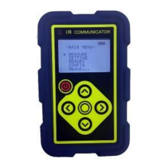
[TS19‐005] 2.1.2 Setting Unit dimensions and nomenclature FIG 2 Setting Unit ‐ 4 ‐ ... -
Page 12: Specifications
[TS19‐005] 3. Specifications 3.1 Specifications 3.1.1 Pressure Switch specifications TABLE 2 General specifications Description Specifications Pressure range 0 to 1MPa, 0 to 10MPa, 0 to 25MPa, 0 to 35MPa, 0 to 50MPa 1 Absolute max. pressure Double pressure range, but 1.5times at pressure ranges 35MPa or above Connection thread R1/4, G 1/4A, G3/8A Rated power source voltage 9 to 36VDC Consumption current Less than 30mADC (no load) Output specification Open collector output Output contact points 2 NPN, less than DC36V; PNP, power source voltage range Output capacity Output capacity may vary with operating temperature. See FIG 3. Response Less than 1ms Repeatability ±0.2% F.S. ±(0.5%F.S. + 1 count) Setting accuracy Including linearity, hysteresis ... - Page 13 [TS19‐005] TABLE 3 Enviromental and structural specifications Description Specifications Operating temperature range ‐20 to 70°C (no freezing, no condensation) 85% RH or less when pressure range for pressure range less than Operating humidity range 2MPa (no freezing, no condensation) Storage temperature and humidity range ‐30 to 80°C, 95% or less (no freezing, no condensation) Withstand voltage 250VAC at 1 minute, fitting to input/output terminals collectively 100MΩ or more (at 50VDC), fitting to input/output terminals Insulation resistance collectively Vibration resistance 300m/s , 10 to 2,000Hz, JIS C 60068‐2‐6 1,000m/s2; 6ms; X,Y,Z forward and reverse direction, 3 times; Impact resistance JIS C 60068‐2‐27 Indoor use Case construction (Protection class: IP67. However IP65 at 1MPa, JIS C 0920) Case material SUS304, PES resin Diaphragm: SUS630 Wetted material Fitting: SUS304, SUS 630 (connection thread for above 20MPa: G1/4A) Orifice: S45C Material of protective cap ...
-
Page 14: Factory Default Settings
[TS19‐005] 3.2 Factory default settings TABLE 5 and TABLE 6 show the factory default settings of the Pressure Switch and Setting Unit respectively. As output polarity, setting pressure and deadband differ according to the model, please refer to the reference drawing or delivery specifications. TABLE 5 Pressure Switch factory default settings Description Output specifications Output polarity Varies with model Comparator operation Hysteresis mode Setting pressure Varies with model Deadband Varies with model ON, OFF delay 0s Filter None Key lock Unlock TABLE 6 Setting Unit factory default settings Description Construction IR (infrared communication) int (IR extension cable not used) Sleep time none Backlight ‐9 Contrast 0 ‐ 7 ‐ ... -
Page 15: Functions
[TS19‐005] 4. Functions The following tables list the functions of the Pressure Switch and Setting Unit. TABLE 7 Pressure Switch functions Function/Mode Description Page reference Connector Equipped with M12 (4P) connectors 4.1.1(P.9) Display Displays Pressure Switch operation status with power source LED/output LED. 4.1.2(P.9) Comparator Hysteresis or window comparator operation 4.1.3(P.10) TABLE 8 Setting Unit functions Function/Mode Description Page reference Search Acquire serial no. of Pressure Switch to be set 4.2.1(P.11) (SEARCH) Pressure, deadband 4.2.2 1) (P.11) Comparator ON/OFF delay setting 4.2.2 2) (P.12) Output polarity Setting Comparator operation mode 4.2.2 3) (P.12) (SETTING) Filter Special function 4.2.2 4) (P.12) ... -
Page 16: Pressure Switch Functions
[TS19‐005] 4.1 Pressure Switch functions 4.1.1 Connector functions The Pressure Switch incorporates an M12 (4 pole) connector for input/output. The pin arrangement and terminal functions of the M12 connector are described in TABLE 9. TABLE 9 M12 connector terminal functions Terminal Pin layout Description Function no. + Power input 1 Power source + Output common (NPN) 2 Output 2 (OUT2) Open collector – Power input 3 Power source – Output common (PNP) 4 Output 1 (OUT1) Open collector 4.1.2 Display function The operational status of the Pressure Switch can be checked by the LEDs on the Pressure Switch, by confirming the color of the LED and whether it is ON or OFF. Functions of each LED are listed in TABLE 10. TABLE 10 LED functions LED layout ... -
Page 17: Fig 4 Hysteresis Mode Operation
[TS19‐005] 4.1.3 Comparator function The comparator function compares the pressure that is applied to the stainless steel diaphragm of the Pressure Switch against a determination pressure value that is set in the Pressure Switch to turn it ON or OFF. Two comparator operating modes ‐ hysteresis mode and window comparator mode ‐ can be selected. Use the Setting Unit to set the comparator operating mode. Hysteresis mode operation In the Hysteresis mode the setting pressure can be set as the upper limit or lower limit, depending on the deadband setting. “Upper limit setting” When you select a positive number (including 0) for the deadband (⊿P), the comparator will operate with the setting pressure (P) as the upper limit. “Lower limit setting” When you select a negative number for the deadband (⊿P), the comparator will operate with the setting pressure (P) as the lower limit. Upper limit setting Lower limit setting FIG 4 Hysteresis mode operation Window comparator mode operation With operation in the Window comparator mode, comparator operation varies depending on how large or small the setting pressure (b) is relative to setting pressure (A). A deadband differential of 1% F.S. is automatically set internally between setting points (A) and (b). In the case that setting pressure (A) ≦ setting pressure (b), the comparator will be ON between (A) and (b). In the case that setting pressure (A) ... -
Page 18: Setting Unit Functions
[TS19‐005] Setting Point (A) Setting Point (b) FIG 6 Deadband of setting points (A), (b) 4.2 Setting Unit functions 4.2.1 Search function To establish infrared communication between the Setting Unit and Pressure Switch for measurement and setting, the Setting Unit must acquire the serial number of the Pressure Switch via the IR connection. In addition to acquiring the serial number, the Setting Unit at the same time also reads‐in the Pressure Switch’s pressure range and settings (pressure, deadband, output polarity, comparator operation settings). When communicating with another Pressure Switch, the serial number of that Pressure Switch must first be similarly acquired. 4.2.2 Setting Various Pressure Switch settings are performed with the Setting Unit’s setting functions. These are detailed in TABLE 11. In the setting operation, if the Pressure Switch is not recognized by the Setting Unit, the search function described in 4.2.1 is activated to establish the IR communication link between the Pressure Switch and Setting Unit. Pressure Switch settings are changed depending on the content of the various settings transmitted by the Setting Unit. TABLE 11 Functional settings Function Settings and Selections Pressure, deadband Set detection pressure of Hysteresis or Window comparator modes. (COMPARATOR) Delay time Set comparator ON or OFF delay time (DELAY (On, Off)) Output polarity Select output polarity (NPN/PNP) ... - Page 19 [TS19‐005] Pressure, deadband setting (COMPARATOR) Reference TABLE 12 and set the detection pressure for the Hysteresis mode or the Window comparator mode. TABLE 12 Comparator pressure setting Comparator mode ...
- Page 20 [TS19‐005] 4.2.3 Measurement (MEASURE) Measurement functions are described in TABLE 14. In the measurement mode, it is necessary to maintain constant infrared connection between the Pressure Switch and Setting Unit in order for the Setting Unit to acquire information from the Pressure Switch in real time. If infrared communication is disconnected for more than 1 minute, measurement mode will be cancelled but the connection information with the Pressure Switch will be retained in the Setting Unit so measurement can be resumed once communication is reestablished. TABLE 14 Measurement functions Function Description Pressure measurement Realtime display of measured pressure (PRS) Change setting pressure Hysteresis mode: setting of set point, deadband (SET) Window comparator mode: setting of set point A, b Zero point adjustment Zero point adjustment (ADJ) Maximum pressure measurement Display or clear (CLR) maximum pressure value measured (TOP) Minimum pressure measurement Display or clear (CLR) minimum pressure value measured (BTM) Loop check Check comparator operation without applying pressure (LPC) Pressure measurement (PRS) This function measures the pressure applied to the Pressure Switch and displays the value in real time. Infrared communication status, comparator operation, and pressure measurement values are displayed in real time. The detection pressure value set in the Pressure Switch is also displayed. Change pressure setting (SET) ...
-
Page 21: Fig 7 Battery Life Indicator Icon
[TS19‐005] 4.2.4 Memory (MEMORY) With the memory function, it is possible to save, edit, and create new setting values for the Pressure Switch. It is also possible to write the saved settings from one Pressure Switch to another Pressure Switch. The maximum number of storable data is 12. The stored values are set in the Pressure Switch with the search function and the Setting Unit and Pressure Switch infrared link. This connection cannot be made to a Pressure Switch with a different pressure range. 4.2.5 Configuration (CONFIG) With the device configuration setting function, set the environment of the Setting Unit. TABLE 15 describes the configuration settings. “BackLight” sets the brightness of the LCD backlight. Consumption current of the Setting Unit will increase with a brighter backlight setting and shorten battery usage time. Make settings that are appropriate to the operating environment. The factory default “BackLight setting” is “‐9”. TABLE 15 Setting Unit configuration settings Setting Setting value Select IR communication method IR communication (Ir) Ir : IR extension cable not used. ext : ... - Page 22 [TS19‐005] 4.2.8 Recharging If nickel‐hydride NiMH batteries are used, the batteries can be recharged using the Setting Unit’s USB port and the USB 2.0 Micro‐B cable connection to a PC or other power source. (Alkaline batteries, if used, cannot be recharged.) During recharging, the charge lamp located at the upper left of the control face of the Setting Unit lights. You can confirm the status of the recharge by this LED. When charging is complete, the charge lamp flashes slowly. ‐ 15 ‐ ...
-
Page 23: Installation And Connections
[TS19‐005] 5. Installation and Connections WARNING Do not attempt to change wiring or insert or disconnect the connector while the product is energized as it could lead to serious accidents. CAUTION When wiring, check the comparator output type (NPN, PNP). If the comparator output type is different, equipment failure may occur. When installing the Pressure Switch in a pressure line, do not install it while the line is filled with liquid. As liquid is incompressible, tightening the pressure fitting could generate high pressures that could damage the Pressure Switch. ... -
Page 24: Connections And Wiring
[TS19‐005] 5.3 Connections and wiring Insert the cable with the M12 connector so that it aligns with the groove of the connector of the Pressure Switch. Firmly tighten the nut manually. Tightening torque: 0.4 to 0.5Nm Insufficient tightening could cause screw loosening by vibration or impair waterproof characteristics. FIG 8 shows the terminal pin arrangement of the M12 connector. Check the connection before turning power ON. Caution should be exercised to make sure that each terminal does not exceed ratings. FIG 8 M12 connector pin arrangement TABLE 17 M12 connector pin function Accessory cable Pin no. Description Function connection color 1 + Power source + Power input, output common (NPN) Brown 2 Output2 (OUT2) Open collector White 3 – Power source – Power input, output common (PNP) Blue 4 ... -
Page 25: Fig 9 Npn Open Collector, Example 1 (Wiring To Relay)
[TS19‐005] 5.4.1 NPN open collector (wiring to relay ) FIG 9 NPN open collector, example 1 (wiring to relay) 5.4.2 NPN open collector (wiring to photo coupler) FIG 10 NPN open collector, example 2 (wiring to photo coupler) 5.4.3 NPN open collector (voltage output) FIG 11 NPN open collector, example 3 (voltage output) ‐ 18 ‐ ... -
Page 26: Fig 12 Pnp Open Collector, Example 1 (Wiring To Relay)
[TS19‐005] 5.4.4 PNP open collector (wiring to relay) FIG 12 PNP open collector, example 1 (wiring to relay) 5.4.5 PNP open collector (wiring to photo coupler) FIG 13 PNP open collector, example 2 (wiring to photo coupler) 5.4.6 PNP open collector (voltage output) FIG 14 PNP open collector, example 3 (voltage output) ‐ 19 ‐ ... -
Page 27: Operation
[TS19‐005] 6. Operation 6.1 Flow of operation The Setting Unit is used to change Pressure Switch settings such as functions and pressure settings. FIG 15 is a flow chart of the operations related to the setting of individual functions. For basic operation, select the measurement, settings, memory and device configuration functions from the main menu of the Setting Unit and make these settings in the Pressure Switch using the infrared communication link. FIG 15 Setting and measurement operation flow chart ‐ 20 ‐ ... -
Page 28: Setting Unit Operation
[TS19‐005] 6.2 Setting Unit operation Setting Unit nomenclature is shown in FIG 16. Control functions are described in TABLE 18. FIG 16 Setting Unit nomenclature TABLE 18 Setting Unit control and display functions Description Function Power ON/OFF switch. Power switch When power is turned ON, company name is displayed then the main menu is displayed. With power ON, press button for more than 3 seconds to enter Sleep mode. To exit Sleep mode, press button for more than 1 second. Sleep button Standby battery power will be consumed in Sleep mode. Switch power OFF if Setting Unit is unused for long periods. LCD Displays measurement values and setting values. Cursor keys Used to switch monitor display for setting changes and selection of operating mode. Enter button Used to input setting changes and selection of operating mode. Recharging LED Lights when nickel‐hydride battery is being recharged. ‐ 21 ‐ ... -
Page 29: Operation
[TS19‐005] 6.3 Operation Pressure Switch methods of operation are listed in TABLE 19. TABLE 19 List of operations Operation Description of operation Page reference Use Pressure Switch with no change in settings. 6.3.1 (P.23) Before setting operation 6.3.2 (P.23) Switch Pressure Switch power ON. 6.3.2 1) (P.23) Switch Setting Unit power ON. 6.3.2 2) (P.23) Attach IR extension cable. 6.3.2 3) (P.24) Change Pressure Switch settings 6.3.3 (P.25) Set output polarity, comparator operation, and filter functions. 6.3.3 2) (P.25) Set setting pressure and deadband. 6.3.3 3) (P.26) Set comparator ON or OFF delay time. 6.3.3 4) (P.27) ... -
Page 30: Fig 17 With Rubber Cap Removed
[TS19‐005] 6.3.1 Using Pressure Switch with no change in settings. Procedure: Install Pressure Switch in accordance with Chapter 5 Installation and Connections. Turn Pressure Switch ON. Check that the power source LED is on. 6.3.2 Steps prior to making settings Switch Pressure Switch power ON Procedure: Remove the rubber cap of the Pressure Switch. The IR transceiver window can be seen when the protective cap is removed. Connect the M12 connector cable to the Pressure Switch and turn power ON. Check that the power source LED is lit. FIG 17 With rubber cap removed Switch Setting Unit power ON Procedure: Remove the Setting Unit cover and open the battery cover on the back of the Setting Unit. Insert batteries. ... -
Page 31: Fig 19 Ir Extension Cable Attachment
[TS19‐005] Attach IR extension cable To use the accessory infrared communication extension cable, attach the extension cable through the main menu of the Setting Unit. The Setting Unit will automatically recognize the IR extension cable. If the IR extension cable is attached or detached without involving the main menu, the Setting Unit will not be able to automatically recognize these actions and the switchover must be done manually. From the standpoint of ensuring infrared communication range as well as operability of the Setting Unit, use of the infrared extension cable is recommended. Procedure: Confirm main menu in the LCD display. When attaching or detaching the IR extension cable other than via the main menu, reference 6.3.6 1) to change settings. Attach the IR extension cable to the IR extension cable connector of the Setting Unit. The main menu will display “ext”. (When the IR extension cable is detached, the “ext” indicator switches off.) Confirm that the power source LED on the IR extension cable clip is ON. Attach the clip of the IR extension cable to the Pressure Switch. (see FIG 19) ... -
Page 32: Fig 20 Main Menu To Setting Menu Screen Display Example
[TS19‐005] 6.3.3 Change Pressure Switch settings Move to the setting menu screen Procedure: Select “SETTING” in the main menu and press the ENTER button. In the search screen, select “SEARCH” and press the ENTER button. Move the IR transceiver windows on the Pressure Switch and Setting Unit close to each other. “CONNECT...” and “OK” is displayed when the Pressure Switch is detected. If the Pressure Switch is not detected, “can not find” is displayed. Select “SEARCH” and do again. When the serial number of the Pressure Switch is displayed, select “OK” and press the ENTER button. The setting menu is displayed. FIG 20 Main menu to setting menu screen display example Set output polarity, comparator operation and filter functions (FUNCTION) Procedure: Select setting (SETTING) from the main menu and press ENTER. If the search screen is displayed, refer to6.3.3. 1). ... -
Page 33: Fig 22 Comparator Setting Screen Example
[TS19‐005] Set setting pressure and deadband (COMPARATOR) Procedure: Select setting (SETTING) from the main menu and press ENTER. If the search screen appears, refer to 6.3.3. 1). Select “COMPARATOR” with the setting menu and press the ENTER button. In the COMPARATOR screen, use the up and down cursor keys to select the setting to be changed. The selected item will appear in reverse black and white. With the left and right cursor keys, select “SET” and press the ENTER button. The value of the setting to be changed is underlined. Set the pressure value using the up and down cursor keys and press the ENTER button. To transmit the setting value to the Pressure Switch. Under “SEND1” press the ENTER button for more than 3 seconds and move the IR transceiver windows of the Pressure Switch and Setting Unit close together. Maintain IR communication until “OK” appears in the LCD display. “E‐3” is displayed if out of IR communication range. To terminate function setting, select “ “ and press the ENTER button to return to the setting menu. FIG 22 COMPARATOR setting screen example ... -
Page 34: Fig 23 Delay (On, Off) Screen Display
[TS19‐005] Set delay time setting (DELAY (on, off)) Procedure: Select setting (SETTING) from the main menu and press ENTER. If the search screen appears, refer to 6.3.3. 1). Select “DELAY (on, off)” with the setting menu and press the ENTER button. In the DELAY screen, use the up and down cursor keys to select the delay time to be changed. The selected item will appear in reverse black and white. With the left and right cursor keys, select “SET” and press the ENTER button. The value of the setting to be changed is underlined. Set the delay time (0 to 2.00s) using the up and down cursor keys and press the ENTER button. To transmit the setting value to the Pressure Switch. Under “SEND1” press the ENTER button for more than 3 seconds and move the IR transceiver windows of the Pressure Switch and Setting Unit close together. Maintain IR communication until “OK” appears in the LCD display. “E‐3” is displayed if out of IR communication range. To terminate function setting, select “ “ and press the ENTER button to return to the setting menu. FIG 23 DELAY (ON, OFF) screen display Special setting (SPECIAL) ... -
Page 35: Fig 24 Special Screen Display
[TS19‐005] FIG 24 SPECIAL screen display 6.3.4 Save and edit setting data Create new setting data (FILE), editing (EDIT) and writing‐in saved data FIG 25 shows the Procedure related to creation of new setting data, editing of saved data and writing‐in of data settings. FIG 25 Steps to create new setting data, editing and writing saved data ‐ 28 ‐ ... -
Page 36: Fig 26 Save Settings
[TS19‐005] Copy (COPY) settings Save setting values that were just edited and read‐in. Procedure: To copy values set in the Pressure Switch, select “SETTING” in the main menu and with the “SEARCH” function, communicate with the corresponding Pressure Switch. This will read‐in the Pressure Switch data. Select “MEMORY” with the main menu and press the ENTER button. In the MEMORY screen, select the FILE No of the file to be saved. The serial number of the Pressure Switch that is displayed above the center of the screen will be the name of the saved file. (If you have edited the setting data with another file name, that file name is used.) If the settings cannot be read‐in, “NO Data” is displayed. Select “COPY” and press the ENTER button for more than 3 seconds. When copying is completed, "DATA COPY OK" is displayed and the display returns to the memory screen. To write copied data to another Pressure Switch, write‐in the data in accordance with the edit (EDIT) flow procedure outlined in 6.3.4. 1). FIG 26 Save settings ‐ 29 ‐ ... -
Page 37: Fig 27 Measurement Mode Operation Flow Chart
[TS19‐005] 6.3.5 Pressure measurement During measurement, it is important to maintain constant infrared communication between the Pressure Switch and Setting Unit. As such use of the accessory infrared extension cable is recommended. The flow chart of operation in the measurement mode is shown in FIG 27. FIG 27 Measurement mode operation flow chart Pressure measurement (PRS) Procedure: In the main menu, select “MEASURE” and press the ENTER button. In the search screen, select “SEARCH” and push the ENTER button. Move the IR transceiver windows of the Pressure Switch and Setting Unit close together. “CONNECT ..”, “OK” is displayed when the Pressure Switch is detected. If the Pressure Switch is not detected, “can not find” is displayed. Select “SEARCH” and do over. When the serial number of the Pressure Switch is displayed, select “OK” and press the ENTER button. Screen switches to the pressure measurement screen (PRS), and the pressure display switches from “WAIT” to “Measured value”. ... -
Page 38: Fig 28 Measurement Mode Display
[TS19‐005] FIG 28 Measurement mode display Change pressure setting (SET) Procedure: In the Pressure Measurement (PRS) screen, select "SET" with the left and right cursor keys and press the ENTER button. The cursor moves to the setting pressure item. (The setting pressure item will appear in reverse black and white. Select the setting pressure to be changed with the left and right cursor keys and press the ENTER button for more than 3 seconds. The value of the pressure setting to be changed is underlined. Setting items will differ with comparator operation. Refer to TABLE 20 of 6.3.3. Change the setting pressure with the up and down cursor keys. With IR communication, there will be a slight time lag at switching of the setting value display. Press the ENTER button for more than 3 seconds. The setting pressure item that was changed will appear in reverse black and white. Press the ENTER button again. Zero point adjustment (ADJ) Procedure: Vent the pressure inlet to the atmosphere。 ... -
Page 39: Fig 29 Top / Bottom Hold / Loop Check Screen Transition
[TS19‐005] Max. pressure display (TOP)/min. pressure display (BTM)/loop check (LPC) operation This series of operations, from maximum pressure display to loop check, are described below. FIG 29 shows the transition in the screen display. Procedure On the measurement pressure display screen, select “PRS” with the left and right cursor keys and press the ENTER button. “TOP” is displayed at the bottom left of the screen and the maximum pressure measured is displayed. Select “CLR” and press the ENTER button for more than 3 seconds to clear the maximum pressure value. Select “ “ and press the ENTER button to return to the measurement pressure display (PRS). Select “TOP” and press the ENTER button. “BTM” is displayed at the bottom left of the screen and the minimum pressure measured is displayed. Select “CLR” and press the ENTER button for more than 3 seconds to clear the minimum pressure value. Select “ “ and press the ENTER button to return to the measurement pressure display (PRS). Select “BTM” and press the ENTER button. “LPC” is displayed at the bottom left of the screen. ... -
Page 40: Fig 30 Infrared Communication Setting Operation
[TS19‐005] 6.3.6 Setting Unit environment settings Infrared communication method (Ir) Procedure: In the main menu, select “CONFIG” and press ENTER. In the CONFIG screen, select “Ir” and press ENTER. The item to be changed is underlined. Use the cursor keys and select “int” or “ext”. “int”: infrared extension cable not used “ext”: infrared extension cable used When the ENTER button is pressed, the underline will disappear and other items can be selected. When “ext” is selected, confirm that “ext” is displayed at the upper left of the screen. When “int” is selected, there is no display at the upper left of the screen. Select “ ” and press ENTER and return to the main menu. FIG 30 Infrared communication setting operation Change time to Sleep mode (SleepTime) Procedure: Select “CONFIG” with the main menu, press ENTER. ... -
Page 41: Fig 31 Device Information Screen Display
[TS19‐005] Change LCD contrast (Contrast) Procedure: Select “CONFIG” with the main menu, press ENTER. In the CONFIG screen, select “Contrast” and press ENTER. The item to be changed is underlined. Use the cursor keys and select contrast. Selectable contrast range: “0 to 15”. Press the ENTER button and the underline will disappear and other items can be selected. Select “ ” and press ENTER and return to the main menu. 6.3.7 Check Setting Unit software version Procedure: Select “About...” with the main menu and press ENTER. The software version of the Setting Unit and battery voltage is displayed for 4 seconds. After 4 seconds, the display returns to the main menu. FIG 31 Device information screen display 6.3.8 End setting operation ... -
Page 42: Fig 33 Recharging Setting Unit
[TS19‐005] 6.3.9 Recharge Setting Unit WARNING Do not use batteries other than nickel hydride (NiMH) batteries for recharging the Setting Unit. Using batteries other than NiMH batteries may cause serious accidents. Check that the battery of the Setting Unit is nickel‐hydride before recharging. Procedure: Turn the power switch ON. Recharge the battery in the main menu display condition or Sleep mode condition. Attach the USB 2.0 micro‐B cable to the USB connector on the top of the Setting Unit. Connect the USB cable to the USB port of a PC or other device that can supply power. Confirm that the charge LED is ON. Charging error is indicated when the LED flashes at a high rate. Disconnect the USB cable and check the batteries. When charging is complete, the recharging LED flashes slowly. Disconnect the USB cable. ... -
Page 43: Storage And Maintenance
[TS19‐005] 7. Storage and Maintenance CAUTION Do not store in the following locations that could result in equipment failure or damage. Locations that expose equipment to water. Locations with atmospheric pressure, temperature, humidity, ventilation, sunlight, dust, salt, air containing sulfur, etc., conditions that could adversely effect the equipment. Locations that are subject to vibration and shock (including during transport). Locations where chemicals are stored and places where gas is generated. Locations exposed to direct sunlight, high temperatures inside vehicles, etc. The detector and circuit of the Pressure Switch have no moving parts. Thus although there is basically no deviation in adjustments, changes related to use over time may occur. As such periodic inspection, about once every six months, is recommended. Refer to the checklist regarding periodic inspection. Checklist: Check outward appearance (scratches, cracks, deformation, corrosion, etc.) Insulation resistance (above 100MΩ at 50VDC) between all input/output terminals and case. Operational check according to pressure reference device and measurement device (check of pressure characteristics, zero point adjustment, etc., can be done with the Setting Unit). ‐ 36 ‐ ... -
Page 44: Troubleshooting
[TS19‐005] 8. Troubleshooting TABLE 21 Troubleshooting Pressure Switch Device Symptom Probable cause Remedy Maintain distance between Setting Power source LED flashes Receiving IR communication Unit and other IR communication (white). devices. Beyond pressure measurement range. Power source LED flashes at a Pressure applied is less than Readjust applied pressure so it falls high rate. –10% F.S. pressure range or within the proper range. exceeds 110% F.S. Change output polarity. – See 6.3.3 2). Change comparator operation. – See 6.3.3 2). Wire correctly according to Wiring error. Comparator does not operate. “Chapter 5 Installation and Power source voltage outside OUT LED does not light. ... - Page 45 [TS19‐005] TABLE 22 Troubleshooting Setting Unit Device Symptom Probable cause Remedy “‐NON” displayed during pressure measurement. IR transceiver windows of the Pressure Switch and Setting Unit Infrared communication “NG” or “E‐3” displayed during should be brought within 300mm severed. data transmission. of each other. “can not find” displayed during SEARCH. Move to the setting mode, establish IR communication to the “NON” displayed during No data to be copied. Pressure Switch with “SEARCH”. MEMORY mode copy. See “6.3.3 1), Move to the setting menu screen”. In case of alkaline batteries, replace Blanked out, blinking battery life batteries. indicator Drop in battery voltage. ...
- Page 46 Contents of this manual are subject to change without notice. Contact us if you require clarification on any contents of this manual. Electronic pressure switch ESW–**–**–10(–L*) Setting unit for electronic pressure switch ESWS–10 Instruction Manual Document no. : TS19‐005 19 Mar. 2019 First edition Issued: Tokyo Keiki Inc. Fluid Power & Control Systems Co. 2‐16‐46, Minami‐Kamata, Ohta‐Ku ...
Need help?
Do you have a question about the ESW Series and is the answer not in the manual?
Questions and answers