Table of Contents
Advertisement
Quick Links
HRT 6145-50
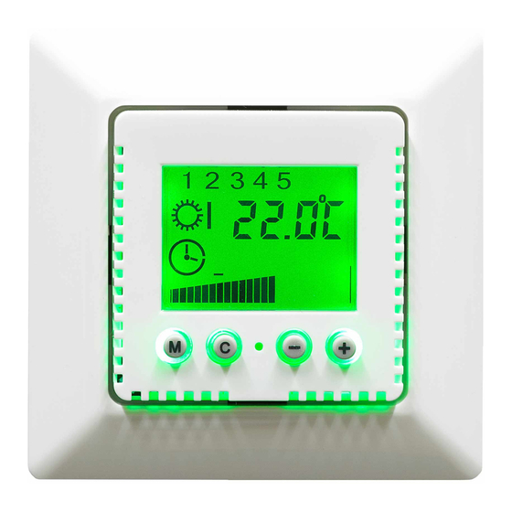
1 2 3 4 5 6 7
_
+
M C
Function
ECOTIMER M is a 10 to 40 °C floor temperature controller with a timer. It enables one or two heating times a day.
Example of one heating time: 6:00 to 22:00 for a living room, Example of two heating times: 6:00 to 9:00 and 17:00 to
22:00 for a bathroom. The reduced heating times with the setback temperature are in between. The set floor temperature
is shown as a ramp at the bottom of the display. It can be changed at any time during heating times by pressing the + or –
buttons. It is also displayed as a numerical value. The actual room temperature is shown as a numerical value on the
display. The setback temperature by which the controller reduces the set floor temperature is programmed once. The
timer can be switched off, and this causes the device to constantly regulate the heating temperature (continuous
operation).
The M button (=Mode) is pressed to set the following operating modes:
Off
Continuous operation
Timer
Freeze stop is active in all operating modes (also in Off mode) and prevents the floor temperature from going below 5°C.
The device has the following factory settings for the timer and the setback temperature:
Setback temperature (temperature value by which the set temperature is reduced during the setback time) 3° C
Start of 1st heating time 6:00 each day
End of 1st heating time 22:00 each day
No second heating time.
Simultaneously pressing M and C resets the device to these factory settings regardless of the current operating mode.
Connecting and commissioning
ATTENTION: Work on the 230 V mains supply must only be carried out by authorised electricians. When connecting the
device, the safety regulations of the VDE (German Association for Electrical, Electronic & Information Technologies) and
the local utility companies must be observed. "Normally closed" valves are required for controlling hot water heating.
TANN L L1
Heating
Floor temperature sensor
may be present on the sensor line. may be present on the sensor line.
TA (not assigned)
ECOTIMER M Floor temperature controller
Setting range approx.
Mains voltage:
Switching current (max.) approx.
Switching capacity
Switch temperature differential:
Temperature sensor:
Perm. ambient temperature:
Connection cables:
Energy class:
(empty circle shown on left of display)
(circle with centre displayed on left of display)
(clock symbol displayed on left of display)
.
Mounting: The temperature controller is mounted in a standard Ǿ 55 mm conduit box
L N PE
(to DIN 49073, part 1). When using additional intermediate terminals, use of a deep
conduit box is recommended. The device is connected according to the circuit diagram
shown. The connection cables must be straight and must be stripped by approx. 5 mm.
Mounting height approx. 1.5 m above the floor. Attention! Fit the support ring above the
wallpaper and mount the controller on the conduit box using the self-tapping screws.
Then place the frame on the conduit box.
Attention: Before pushing on the cover plate, ensure that the internal sensor (bottom
left) is pointing diagonally downwards. The sensor should not touch the controller
housing. The floor temperature sensor must be laid in a protective tube at heating mat
level in the centre between the heating mats. The sensor cable must be laid in a
separate protective tube and must not be laid together with the power supply cables
Danger: Avoid electric shock. Be aware that in the event of a fault, the power
10 to 40°C
230 V ~ ± 10% , 50 Hz
12 (4) A
2.7 kW
0.7 K
NTC to DIN 44574
4 m long
-10 to +40°C
2
2.5 mm
VII = 3.5%
Advertisement
Table of Contents

Related Manuals for HRT ECOTIMER M

Summary of Contents for HRT ECOTIMER M
- Page 1 Function ECOTIMER M is a 10 to 40 °C floor temperature controller with a timer. It enables one or two heating times a day. Example of one heating time: 6:00 to 22:00 for a living room, Example of two heating times: 6:00 to 9:00 and 17:00 to 22:00 for a bathroom.
- Page 2 Programming Programming is always started by entering the time, weekday, and setback temperature. The switch times are then set. Do not start any programming (press button C briefly) before 88:88 (flashing) appears in the display. The programming can be cancelled at any point. If, for example, only the time needs to be adjusted for a DST time change, simply set the time and then stop any further programming.
Need help?
Do you have a question about the ECOTIMER M and is the answer not in the manual?
Questions and answers